Device for treating disc-like article and method for operating same

Inactive Publication Date: 2011-10-13
LAM RES AG
View PDF8 Cites 26 Cited by
  • Summary
  • Abstract
  • Description
  • Claims
  • Application Information

AI Technical Summary

Benefits of technology

[0046]To obtain a perfect thermal insulation of the HTS-material a high gradient thermal super-isolation technology with temperature gradients up to 200 K/mm has been developed and tested. The highly compact insulation structure reduces cryogenic effort an

Problems solved by technology

This results in a low wall thickness.
Furthermore such active bearing and drive mechanism m

Method used


Image

  • Device for treating disc-like article and method for operating same
  • Device for treating disc-like article and method for operating same
  • Device for treating disc-like article and method for operating same

Examples


first embodiment

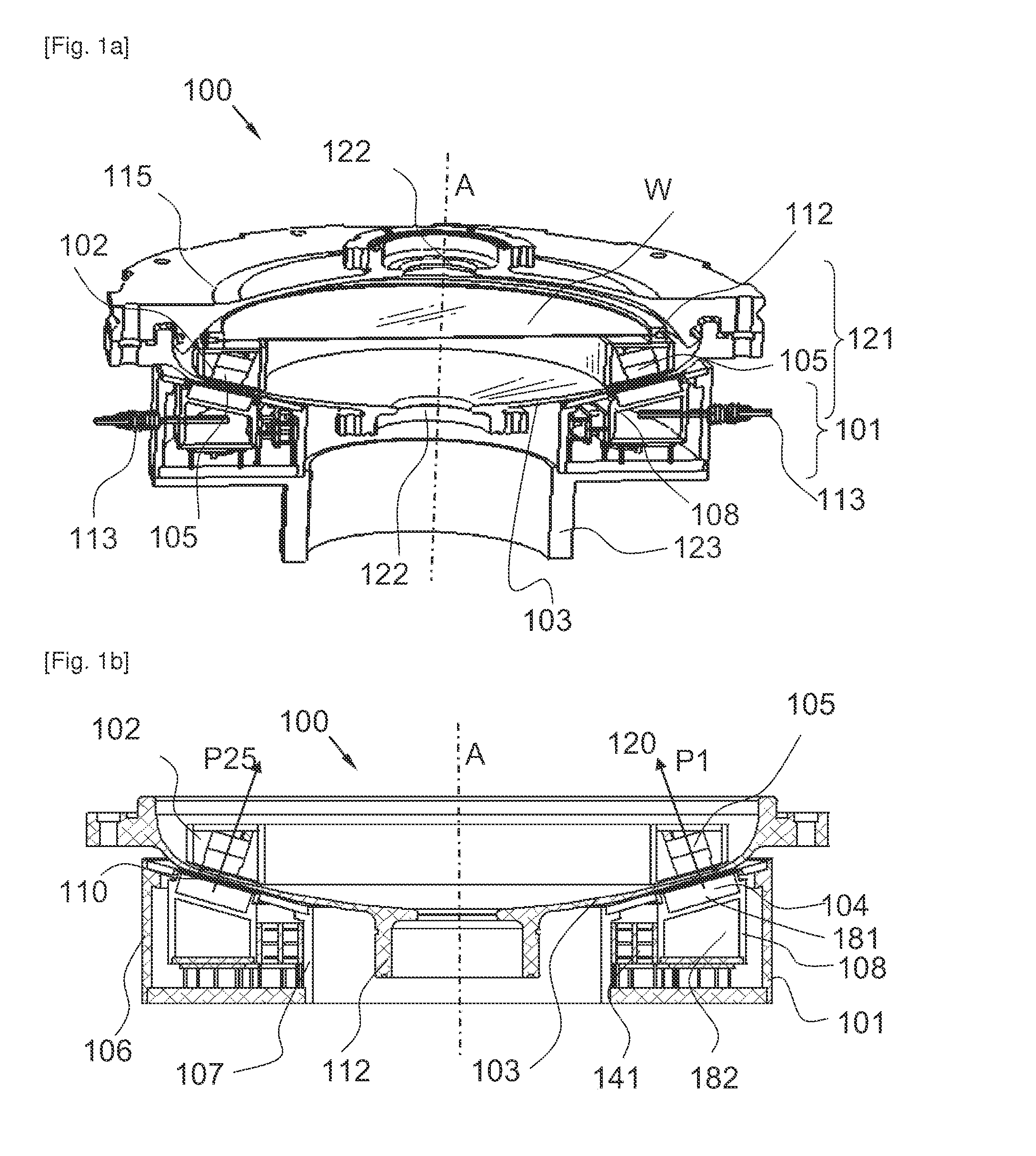
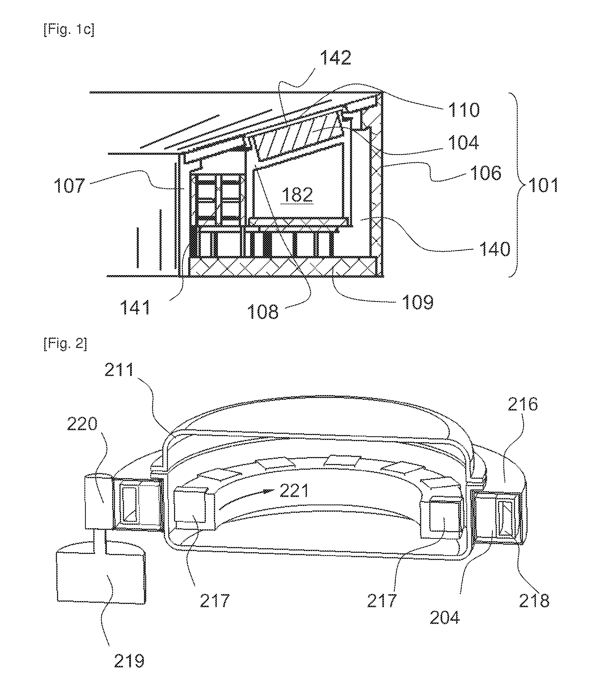
[0058]With reference to FIGS. 1a, 1b, and 1c is the invention shall be described. A magnetic levitated system 100 operates through the bottom 103 of the semiconductor processing chamber 121. The silicon wafer W is fixed on a magnetic wafer carrier 112 and rotated without any mechanical contact in sealed process chamber 121. The process chamber 121 comprises a bottom 103 in the shape of a Kloepper bottom to withstand mechanical forces at lowest wall thickness in case of forces due to high pressure or vacuum in side the process chamber 121. The process chamber 121 is made of stainless steel or non-metallic compound material. The HTS magnetic coupling features a radial symmetric superconducting driving rotor 101 below the chamber and above it with an axial spacing a large driven rotor 102 inside the chamber. Driving rotor 101 and driven rotor 102 are separated by the nonmagnetic chamber wall 103, which is bridged by magnetic forces. The driving rotor 101 has a ring structure with integ...

third embodiment

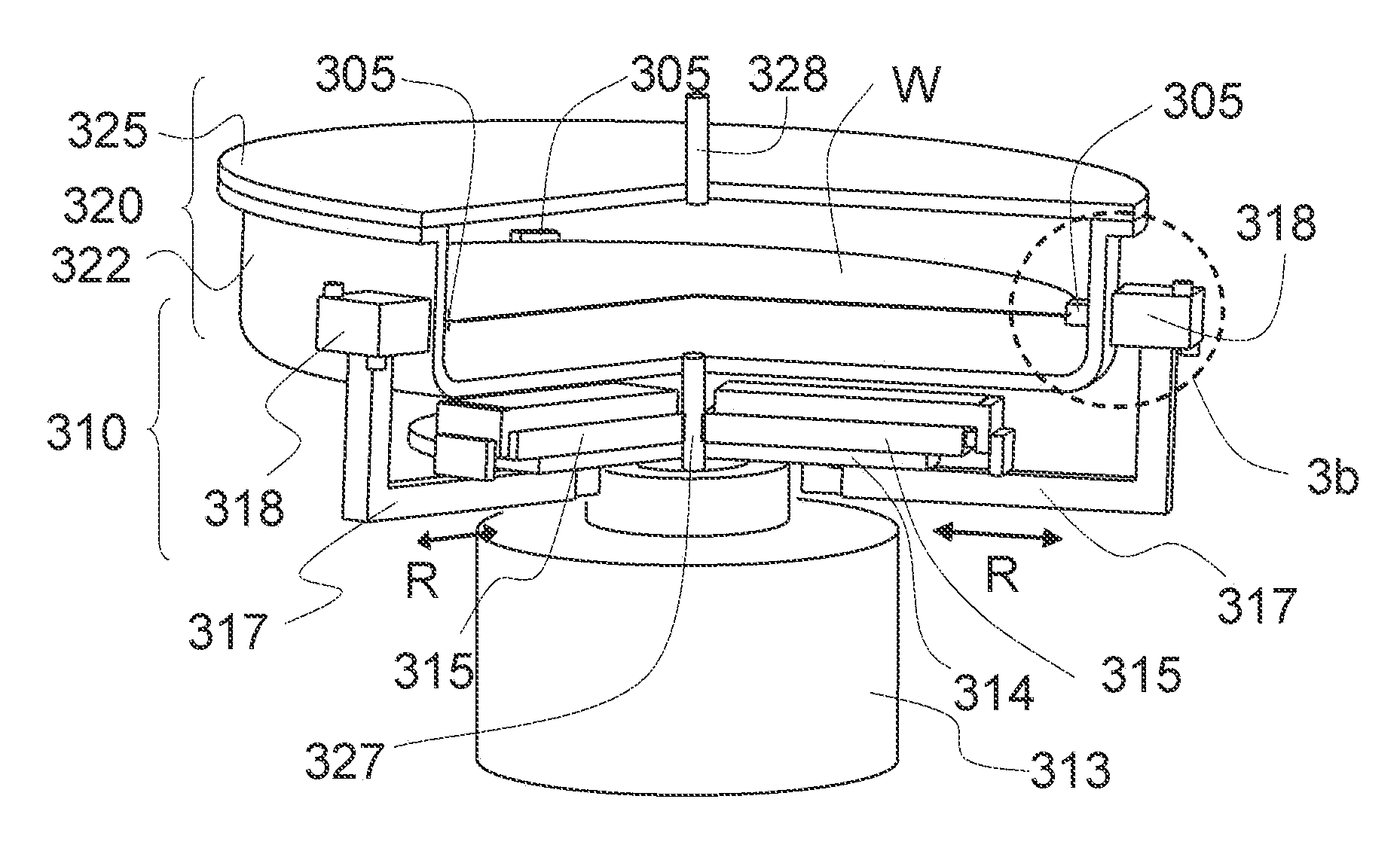
[0082]FIG. 3a shows a schematic cross-sectional perspective view of a

[0083]Detail 3b (dotted line circle) is shown enlarged in FIG. 3b. The device comprises a chamber 320, a driving rotor 310, and a driven rotor 305. The chamber 320 comprises a. bowl 322 with a. basically vertical cylinder-shaped side wall. A feed pipe 327 feeds fluid (liquid and / or gas) to the bowl 322 and an exhaust pipe 328 collects used fluid.

[0084]The driving rotor 310 comprises a rotary disc 314, which is located underneath the bowl 322. The driving rotor 310 is connected to the hollow shaft of a hollow shaft motor 313. The pipe 327 leads through the hollow shaft. Three L-shaped carrier rods 317 are radially slidable mounted to the rotary disc—slidable in a direction perpendicular to the rotation axis of the rotation motion. The linear motion R of the carrier rods 317 is driven by linear modules 315. The L-shaped carrier rods 317 together encompass the bowl 322 so that the distal end of the L-shaped carrier ro...


PUM


Abstract

A device for supporting and rotating a disc-like article includes:
    • a first rotor including a support for supporting the disc-like article, wherein the first rotor is located within a process chamber,
    • a second rotor connected to a drive mechanism for rotating the second rotor, wherein the second rotor is coupled to the first rotor by magnetic forces without touching the first rotor, and the second rotor is located outside the process chamber and a wall is arranged between the first rotor and the second rotor, and
    • at least one magnetic couple, wherein the couple includes a first coupling part and a second coupling part, wherein the first coupling part includes a coupling magnet mounted to the first rotor and the second coupling part includes a high temperature superconducting material,
wherein the magnetic couple(s) are arranged and/or formed so that no degree of freedom remains between the first and second rotor so that the first rotor moves together with the second rotor. A method for operating such device is disclosed.

Description

TECHNICAL FIELD[0001]The invention refers to a device for supporting and rotating a. disc-like article with a rotor comprising a support for supporting the disc-like article, wherein the rotor is located within a process chamber.BACKGROUND ART[0002]WO 2007 / 101764 A1 discloses a device for fluid treatment of a plate-like article comprising a rotary head for holding and rotating a plate-like article around a. rotation axis, drive means to suspend and drive the rotary head without contact, the drive means being arranged radially around the rotary head, a substantially cylindrical wall, which is substantially concentric to the rotation axis, wherein the cylindrical wall is arranged between the rotary head and the drive means.[0003]A suitable driving mechanism is described in U.S. Pat. No. 6,485,531. With the herein disclosed active magnetic bearing and drive mechanism the distance of stator to rotor is limited. This results in a low wall thickness. Furthermore such active bearing and dr...

Claims


Application Information

Patent Timeline
IPC IPC(8): H01L21/683H01L21/68
CPCH01L21/683H01L21/68785H01L21/68728H01L21/68735
Inventor OBWEGER, RAINERWERFEL, FRANK
Owner LAM RES AG
Why Eureka
Try Eureka