Plasma oxidation method and plasma oxidation apparatus

Inactive Publication Date: 2011-10-13
FUJIFILM CORP +1
View PDF1 Cites 6 Cited by
  • Summary
  • Abstract
  • Description
  • Claims
  • Application Information

AI Technical Summary

Benefits of technology

[0014]The present invention has been contrived in view of these circumstances, an object thereof being to provide a plasma oxidation method and a plasma oxidation apparatus capable of oxidizing a thick film, while also enabling oxidation at low temperature by improving the oxidation rate even in cases where the substrate temperature is low.

Problems solved by technology

A method of oxidizing silicon typically employs a thermal oxidation method, but this involves a high processing temperature of 1000° C., and there is a possibility that impurities in the silicon substrate are diffused.
However, in a silicon oxidation method using plasma oxidation, there are few practical examples of low-temperature processing at 400° C. or below, and when processing has been performed at a low temperature of 400° C. or below, the oxidation rate has been slow and it has been difficult to create a thick oxide film.
Furthermore, in a plasma oxidation method using positive ions and negative ions, when one of “positive ions” and “negative ions” is used, due to the occurrence of a charging-up phenomenon, the oxidation rate falls and it is difficult to oxidize a thick film.
In this way, according to a method which applies one of a positive bias and a negative bias, in other words, a method applying a DC (direct current) bias, a charging-up phenomenon occurs and it is difficult to form a thick oxide film, and furthermore, there is a problem of poor productivity due to the low oxidation rate.
However, if a DC voltage is applied to a substrate, there is a possibility that a charging-up phenomenon may occur due to attraction of one of the positive ions and negative ions.
Moreover, due to effects of the charging-up phenomenon, as well as being difficult to form a thick oxide film, the oxidation rate is low and productivity is poor.
However, if the substrate potential is controlled by a variable impedance, then it is not possible to control the value of the self-bias voltage Vdc, to a positive potential, and furthermore, the value of Vdc changes simultaneously with the control of the peak-to-peak voltage Vpp.
Therefore, since Vdc and Vpp cannot be controlled individually, there are limitations on the range of the oxidation conditions, and consequently, it is difficult to achieve a thick oxide film and to improve the oxidation rate.
However, if only negative ions are used, then there are possibilities that it is difficult to achieve a thick film due to the occurrence of a charging-up phenomenon, and the oxidation rate is low.
Furthermore, if the peak-to-peak voltage Vpp during oxidation and the self-bias voltage Vdc are too high, then plasma forms in the vicinity of the stage and it is difficult to achieve oxidation which causes little damage.
Moreover, in Japanese Patent Application Publication No. 2002-280369, bias application frequencies of 400 kHz and 1 MHz are used, and in the case of the lower frequency, the oxide film becomes a capacitor and it becomes difficult to apply the bias.
Therefore, when forming a thick oxide film, it is difficult to obtain the effects of applying the bias, and therefore it is difficult to obtain a thick film.

Method used


Image

  • Plasma oxidation method and plasma oxidation apparatus
  • Plasma oxidation method and plasma oxidation apparatus
  • Plasma oxidation method and plasma oxidation apparatus

Examples


Embodiment Construction

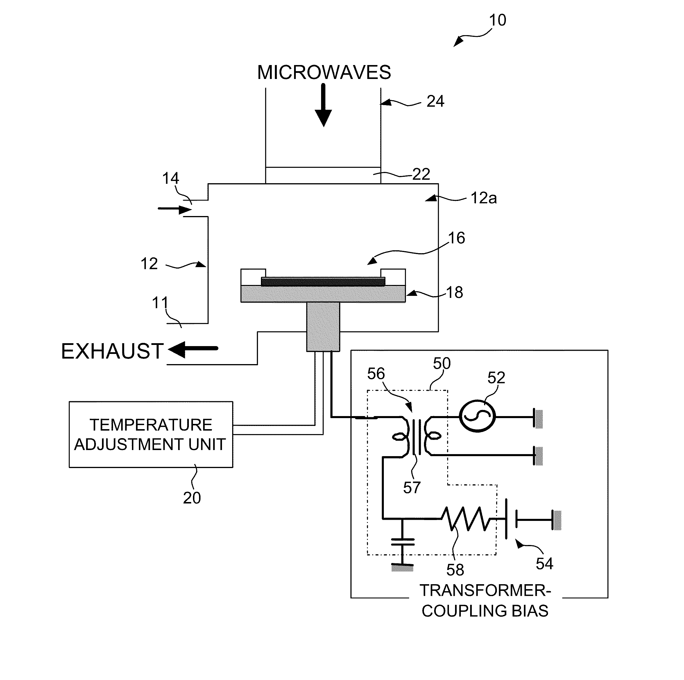
[0049]FIG. 1 is a cross-sectional drawing showing the composition of a plasma oxidation apparatus relating to one embodiment of the present invention.

[0050]As shown in FIG. 1, this plasma oxidation apparatus 10 comprises a vacuum chamber 12 (vacuum vessel); a process gas introduction section 14 is provided in the upper part of the vacuum chamber 12 and a process gas for producing plasma is introduced via this introduction section 14. Although not shown in the drawings, a mass flow controller (MFC) is provided with the process gas introduction section 14 in such a manner that process gas is supplied to the interior of the vacuum chamber 12 while the flow volume of the process gas is controlled.

[0051]Furthermore, an exhaust section 11 comprising an exhaust pump (not illustrated), and a pressure adjustment mechanism (not illustrated), are connected to the vacuum chamber 12, and the gas flow volume and the processing pressure used in the plasma oxidation processing can be adjusted by me...


PUM

PropertyMeasurementUnit
Temperatureaaaaaaaaaa
Electric potential / voltageaaaaaaaaaa
Bias potentialaaaaaaaaaa

Abstract

A plasma oxidation method includes the steps of: generating oxygen-containing plasma with a process gas containing oxygen; applying a bias voltage to a substrate placed on a stage; and radiating positive ions and negative ions in the oxygen-containing plasma onto the substrate so as to perform plasma oxidation of the substrate while controlling a bias potential of the substrate in such a manner that a maximum value Vmax and a minimum value Vmin of the bias potential and a plasma potential Vp satisfy a following relationship: Vmin<Vp<Vmax.

Description

BACKGROUND OF THE INVENTION[0001]1. Field of the Invention[0002]The present invention relates to a plasma oxidation method and a plasma oxidation apparatus, and more particularly to a plasma oxidation method and a plasma oxidation apparatus for forming a silicon oxide film by oxidizing silicon through radiating oxygen plasma onto a silicon substrate used in a semiconductor process.[0003]2. Description of the Related Art[0004]In a manufacturing process for a semiconductor apparatus, the process for forming a silicon oxide film on the surface of a silicon substrate by oxidizing the substrate, for example, is important. A method of oxidizing silicon typically employs a thermal oxidation method, but this involves a high processing temperature of 1000° C., and there is a possibility that impurities in the silicon substrate are diffused. Therefore, silicon oxidation methods using plasma oxidation has been proposed.[0005]For example, Japanese Patent Application Publication No. 11-121448 di...

Claims


Application Information

Patent Timeline
IPC IPC(8): H01L21/316C23C16/50
CPCH01L21/02238H01L21/02164
Inventor TAKAHASHI, SHUJISHINDO, HARUO
Owner FUJIFILM CORP
Why Eureka
Try Eureka