

Alumina sintered body
Patent Information
- Authority / Receiving Office
- US · United States
- Current Assignee / Owner
- DENSO CORP
- Publication Date
- 2011-10-13
- Estimated Expiration
- Not applicable · inactive patent
Smart Images
Figure 1 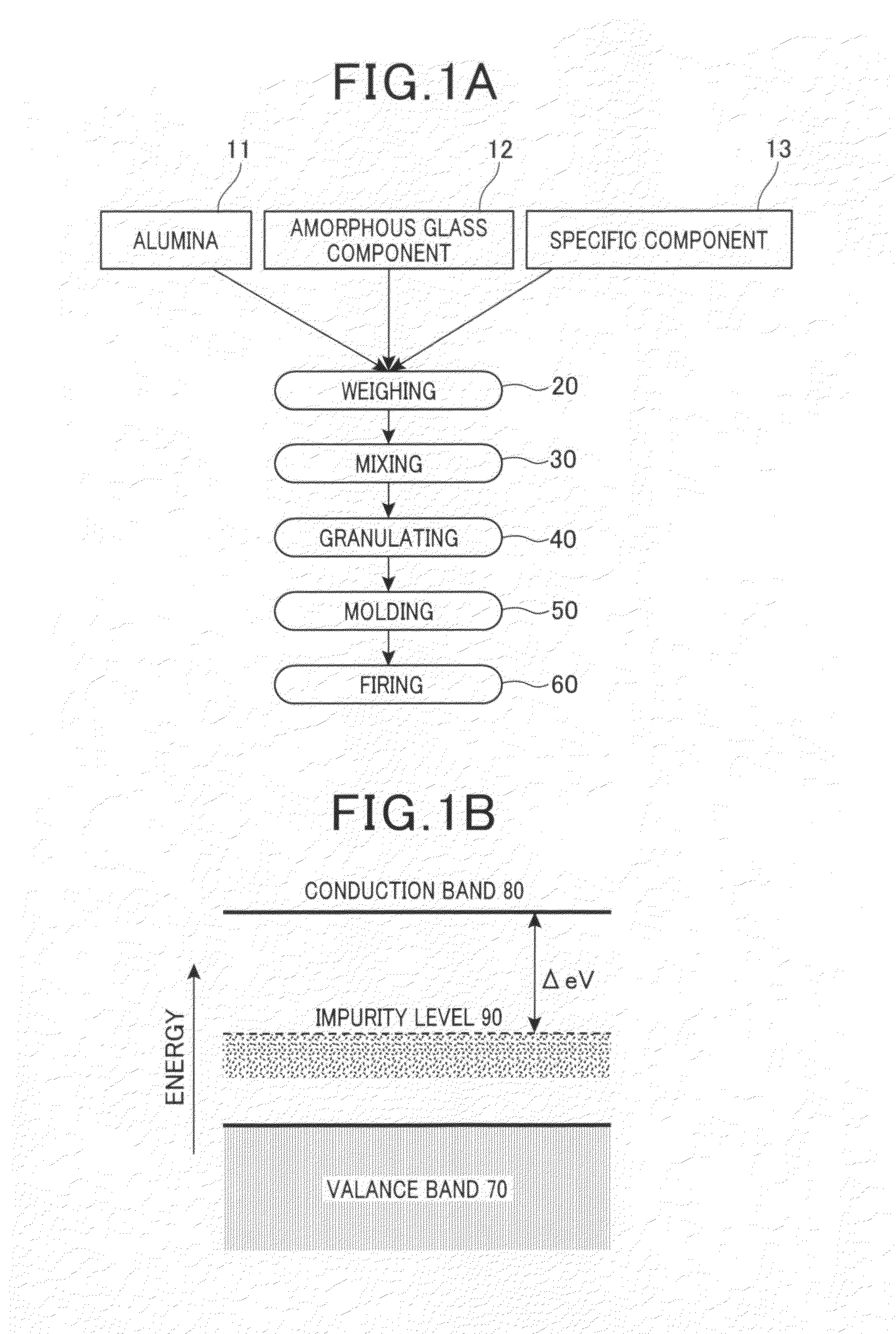
Figure 2 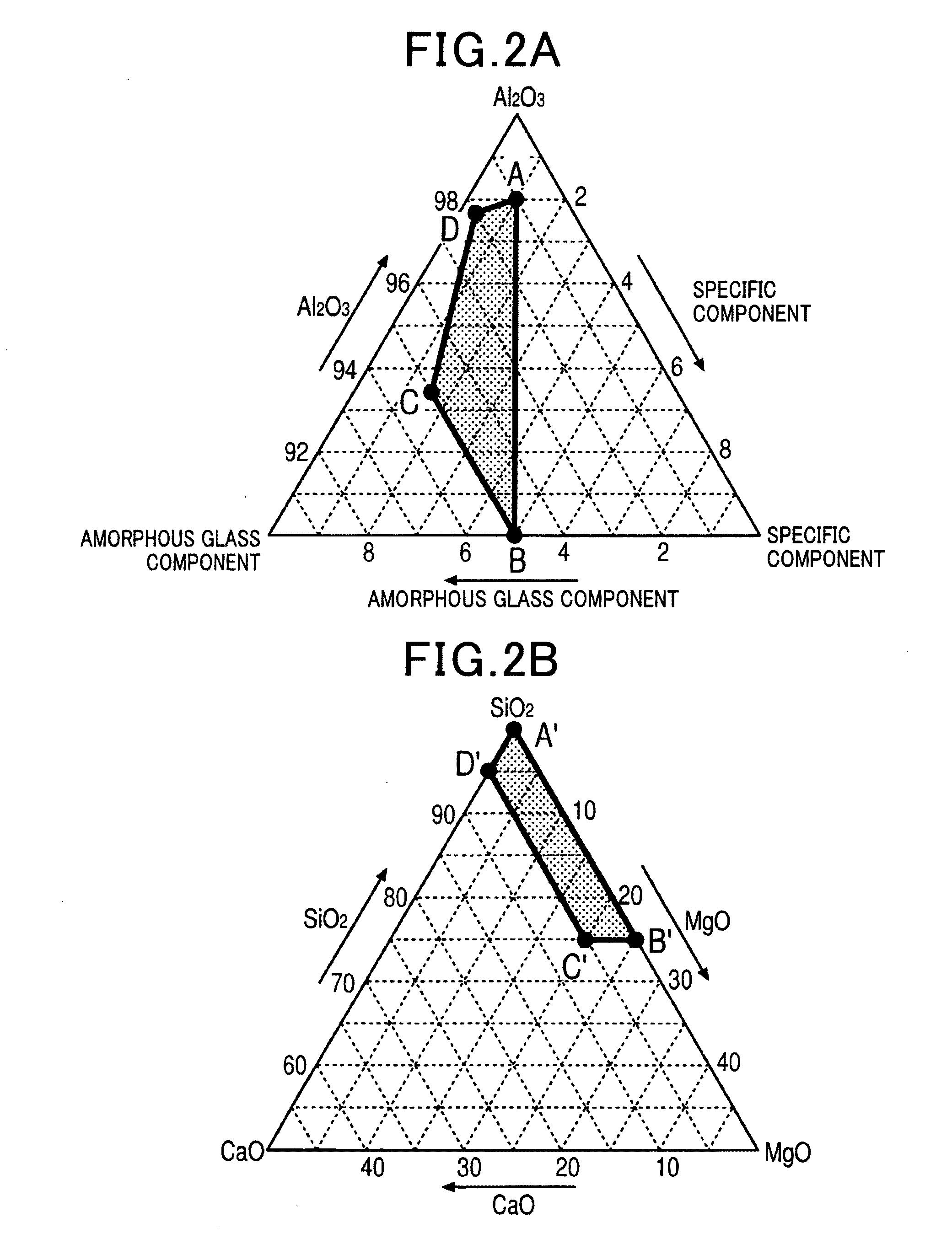
Figure 3
Abstract
Description
CROSS REFERENCES TO RELATED APPLICATIONS
[0001] The present application relates to and incorporates by reference Japanese Patent application No. 2010-089310 filed on Apr. 8, 2010.BACKGROUND CF THE INVENTION
[0002] 1. Field of the Invention
[0003] The present invention relates to an alumina sintered body containing alumina as a main component. In particular, the present invention relates to an alumina sintered body having improved low-temperature sinterability and voltage endurance that can be used in insulators in spark plugs for internal combustion engines, substrates for electronic components, insulating protective elements, and the like.
[0004] 2. Description of the Related Art
[0005] The alumina sintered body is widely used as insulation material for spark plugs in automobile engines, and various substrates and elements, because the alumina sintered body contains alumina (Al2O3) having a physically stable property as a main component, and has excellent insulation and voltage endurance cha...