
Blade-type drill bit

a drill bit and blade-type technology, applied in the field of rock destructing tools, can solve the problems of increasing the weight of drill string, affecting the stability of drilling, and affecting the performance of drilling bit, etc., to achieve optimal rop and steerability of pdc bit, facilitate formation of additional stabilization channels, and reduce the effect of excessive penetration

Inactive Publication Date: 2011-10-20
SCI & PRODION ENTERPRISE LIMITED LIABILITY COMPANY BURINTEKH BURINTEKH
View PDF4 Cites 1 Cited by
  • Summary
  • Abstract
  • Description
  • Claims
  • Application Information

AI Technical Summary

Benefits of technology

[0009]The object of the invention is to improve steerability of the drilling bit whilst increasing the vibration resistance of the PDC bit.

Problems solved by technology

While offloading the drill string from the boring rig, the drill string weight becomes greater than static friction force against the well wall and the “downfall” of the string from the well walls occurs.
This results in a considerable jump in weight on bit (WOB).
Thus, drilling of slant and horizontal wells takes place under conditions of considerable inequity in values of axial stress applied to the bit.
Herewith, excessive introduction of cutters into the formation and marked increase of torque necessary for the bit rotation take place.
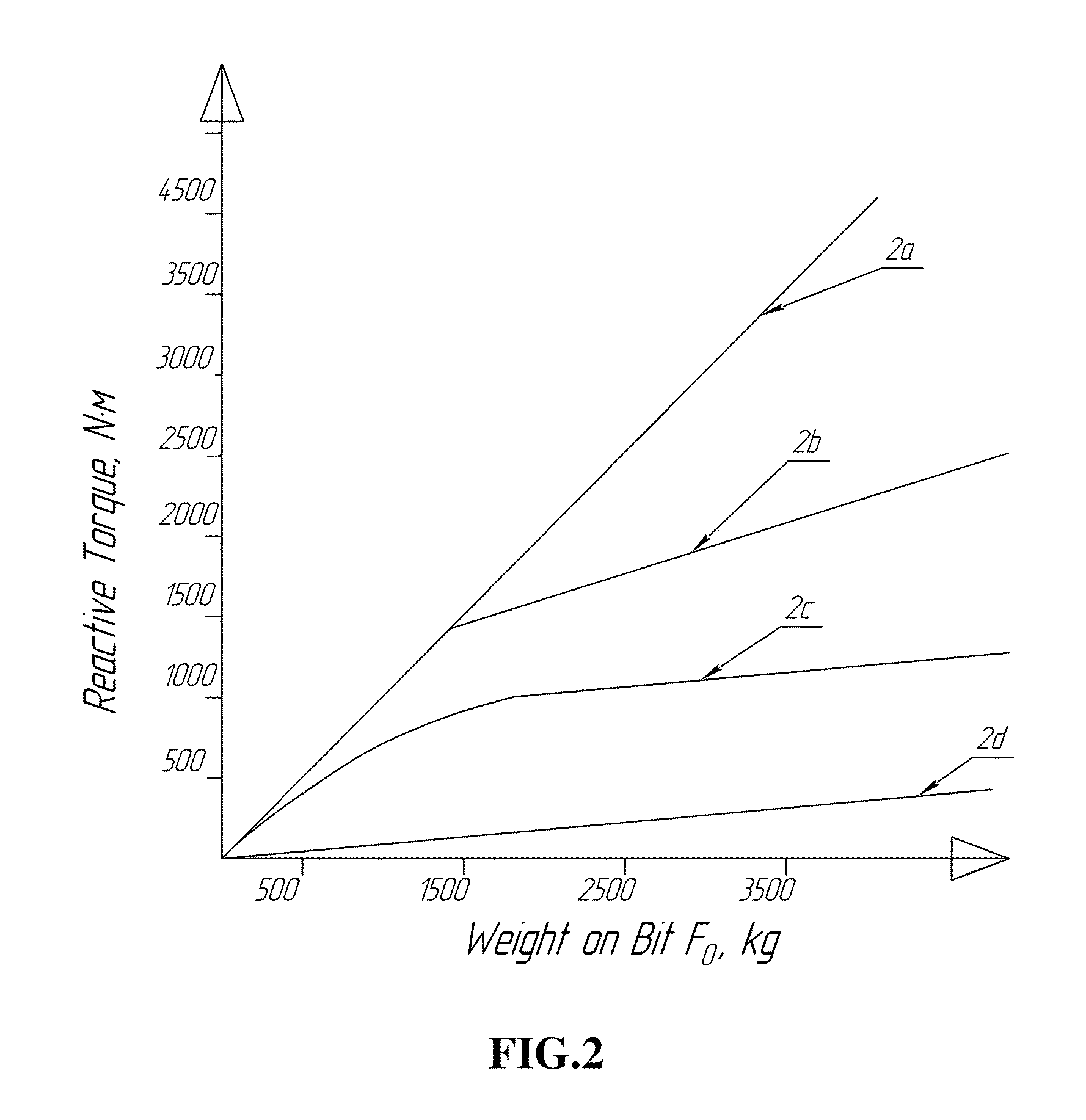
If the bit responds to the axial stress changes with a dramatic change in the required torsional moment necessary for rotation thereof, this leads to the twisting of the drill string and uncontrolled variation of whipstock set-up plane angle against well axis, i.e. loss of steerability.
It is getting difficult, and in some cases impossible, to control the direction of the well drilling.
However, the usage of the knownbit does not solve the problem with drilling of slant and horizontal sections, therefore the torsional moment of the bit still depends highly on the axial stress.
But the disadvantage of such bits lies in sharp changes in the torsional moment depending on the axial stress, as penetration stoppers of smaller sizes easily penetrate into the formation.
High accuracy requirement for installing stoppers height-wise with respect to the cutter can be also be considered a disadvantage of said bits.
The disadvantage of this bit lies in still unsatisfactory load-torque characteristic.
Another disadvantage of said prior art analogue is the constant value of the cutter protrusion over bit blades.
This disadvantage is apparent when drilling slant horizontal sections of wells in formations with interdigitations of layers with different degrees of hardness.
For example, when drilling from a softer interlayer to a harder and solid interlayer, penetration depth of the cutter into the formation decreases, and the contact of blades with the formation is lost, the bit starts to act like a conventional drill bit, and as a result, the steerability decreases.

Method used


Image

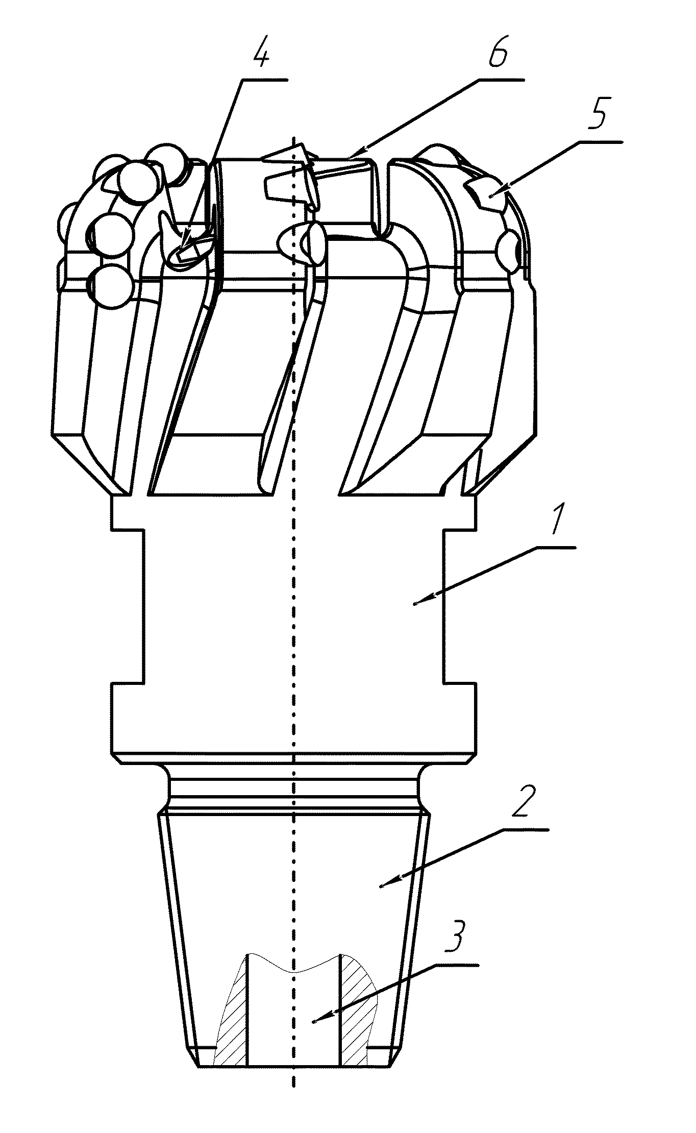
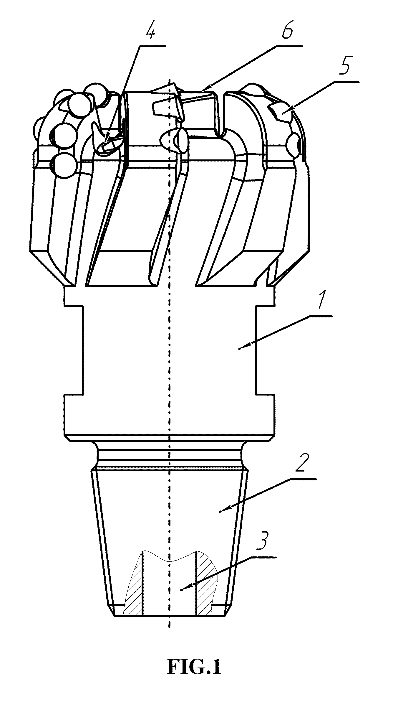
  • Blade-type drill bit
  • Blade-type drill bit
  • Blade-type drill bit

Examples


example 1

[0035]Six-bladed drill bit BIT 220.7 BT 613 (type IADC S333) for drilling soft sandstones and clays was used in the tests. These formations typically have strength varying from 4 to 6 kg / mm2 in the upper interval of the formation and 15-20 kg / mm2 in the lower interval of the drilled formation. The friction angle of these formations usually varies from 44 to 42 in the upper interval and 34 to 36 in the lower interval of the drilled section respectively. The drill bit 220.7 BT 613 is normally used at an average drilling rate from 50 to 70 m / h. The equivalent thrust load required to obtain the said drilling rate at a rotational speed of 280 to 300 rpm, was usually from 5 to 8 t.

[0036]The drilling bit blades were coated by a composite coating of hard alloy according to the invention to obtain the final thickness of about h=3 mm. Hard alloy coating was applied by means of lamination layer by layer by gas-flame spraying of a composite powder material produced by, for example, Technicord, ...

example 2

[0040]According to Example 2, a four-bladed matrix-type drill bit 220.7 BT 416 M (type IADC M333) for drilling soft sandstone and clay was used.

[0041]The drilling bit was used to drill a formation having strength varying from 3 to 5 kg / mm2 in the upper interval and from 12 to 18 kg / mm2 in the lower interval of the drilled section. The friction angle of the formation was from 46-45 in the upper interval and 32-34 in the lower interval of the drilled section respectively. The drill bit of this type is typically designed to achieve average drilling rate from 50 to 70 m / h. The equivalent thrust load to support predetermined drilling rate, at a rotational speed of 180 . . . 220 rpm, was 6 . . . 10 t. The drilling bit was coated to obtain the thickness 4 mm of hard alloy coating on the bit blades.

[0042]The drilling bit was prepared in accordance with the technology for producing matrix bits, in particular, using powder metallurgy. In the course of the process, a layer of the hard alloy co...


PUM

PropertyMeasurementUnit
Thicknessaaaaaaaaaa
Thicknessaaaaaaaaaa
Heightaaaaaaaaaa

Abstract

The invention relates to rock destruction tools used for drilling oil and gas wells, especially for drilling slant and horizontal wells and formations having alternating layers of different hardness. The technical effect consist in improved steerability of the drilling bit and higher vibration resistance of polycrystalline diamond cutters (PDC) bit due to the use of a composite plating applied and adjustment of cutter protrusion over this plating. Blade drilling bit includes body with coupling thread, central channel, exit holes for flushing fluid and blades, equipped with polycrystalline diamond cutters PDC. Blade surface is covered with composite plating having different wear resistance depending on thickness, and tolerance of composite plating to abrasion wear increases from the outer surface to sublayers, and the size of cutter protrusion close to the centre of bit over the surface of composite plating is less than required for drilling the hardest formations in given geological section.

Description

CROSS-REFERENCE TO RELATED APPLICATION[0001]This application claims the benefits from the International Application PCT / RU2009 / 000498 filed on Sep. 28, 2009 and claiming priority from RU 2008152613 of Dec. 12, 2008. The content of these applications is hereby incorporated by reference in its entirety.TECHNICAL FIELD[0002]This invention relates to the rock destructing tool, used for drilling oil and gas wells, especially for drilling of slant and horizontal wells and formations formed as interchanging layers with different degrees of hardness.BACKGROUND OF THE INVENTION[0003]In directional drilling, using downhole motor equipped with axis skewing mechanism or bent sub between power and spindle sections, the “torque-load” characteristic of the drill bit is of great importance. Due to great length of a drill rig and the bends thereof as well as due to an increase in inclination angle of the borehole axis, the weight of the drill string can be distributed on the well sides and not reach...

Claims


Application Information

Patent Timeline
IPC IPC(8): E21B10/46B23K1/00B05D5/00
CPCE21B10/55
Inventor ISHBAEV, GNIYATULLA GARIFULLOVICHBALUTA, ANDREJ GRIGORIEVICHSHARIPOV, ARTUR NAILIEVICH
Owner SCI & PRODION ENTERPRISE LIMITED LIABILITY COMPANY BURINTEKH BURINTEKH
Learn More