
Methods and devices for measuring Raman scattering of a sample

a collection device and sample technology, applied in the direction of measurement devices, instruments, analysis by material excitation, etc., can solve the problems of small sample volume, damage to some delicate samples, and the collection efficiency of raman spectrum may not be very representative, so as to improve the excitation efficiency of raman scattering and enhance the collection efficiency. , the effect of high reflectivity

Active Publication Date: 2018-10-30
METROHM SPECTRO INC
View PDF32 Cites 2 Cited by
  • Summary
  • Abstract
  • Description
  • Claims
  • Application Information

AI Technical Summary

Benefits of technology

The device enhances Raman signal excitation and collection efficiency, providing more representative spectra for non-uniform and diffusely scattering samples, including sub-surface measurements, while minimizing sample damage and improving material characterization.

Problems solved by technology

First, only a small volume of the sample is measured.
Thus the collected Raman spectrum may not be very representative, especially for some non-uniform samples.
Second, the tightly focused laser beam may cause damage to some delicate samples.
Third, for diffusely scattering samples which are not transparent to the laser beam, this approach will only measure the Raman scattering signal from the surface layer of the sample.

Method used


Image

  • Methods and devices for measuring Raman scattering of a sample
  • Methods and devices for measuring Raman scattering of a sample
  • Methods and devices for measuring Raman scattering of a sample

Examples


Embodiment Construction

[0015]Before describing in detail embodiments that are in accordance with the present invention, it should be observed that the embodiments reside primarily in combinations of method steps and apparatus components related to a light delivery and collection device for measuring Raman scattering of a sample. Accordingly, the apparatus components and method steps have been represented where appropriate by conventional symbols in the drawings, showing only those specific details that are pertinent to understanding the embodiments of the present invention so as not to obscure the disclosure with details that will be readily apparent to those of ordinary skill in the art having the benefit of the description herein.

[0016]In this document, relational terms such as first and second, top and bottom, and the like may be used solely to distinguish one entity or action from another entity or action without necessarily requiring or implying any actual such relationship or order between such enti...


PUM

PropertyMeasurementUnit
Ramanaaaaaaaaaa
areaaaaaaaaaaa
reflectivityaaaaaaaaaa

Abstract

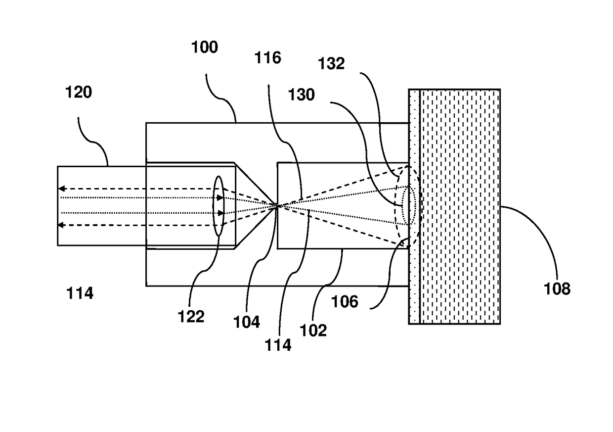
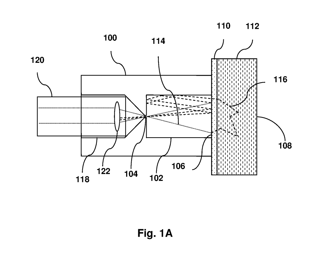
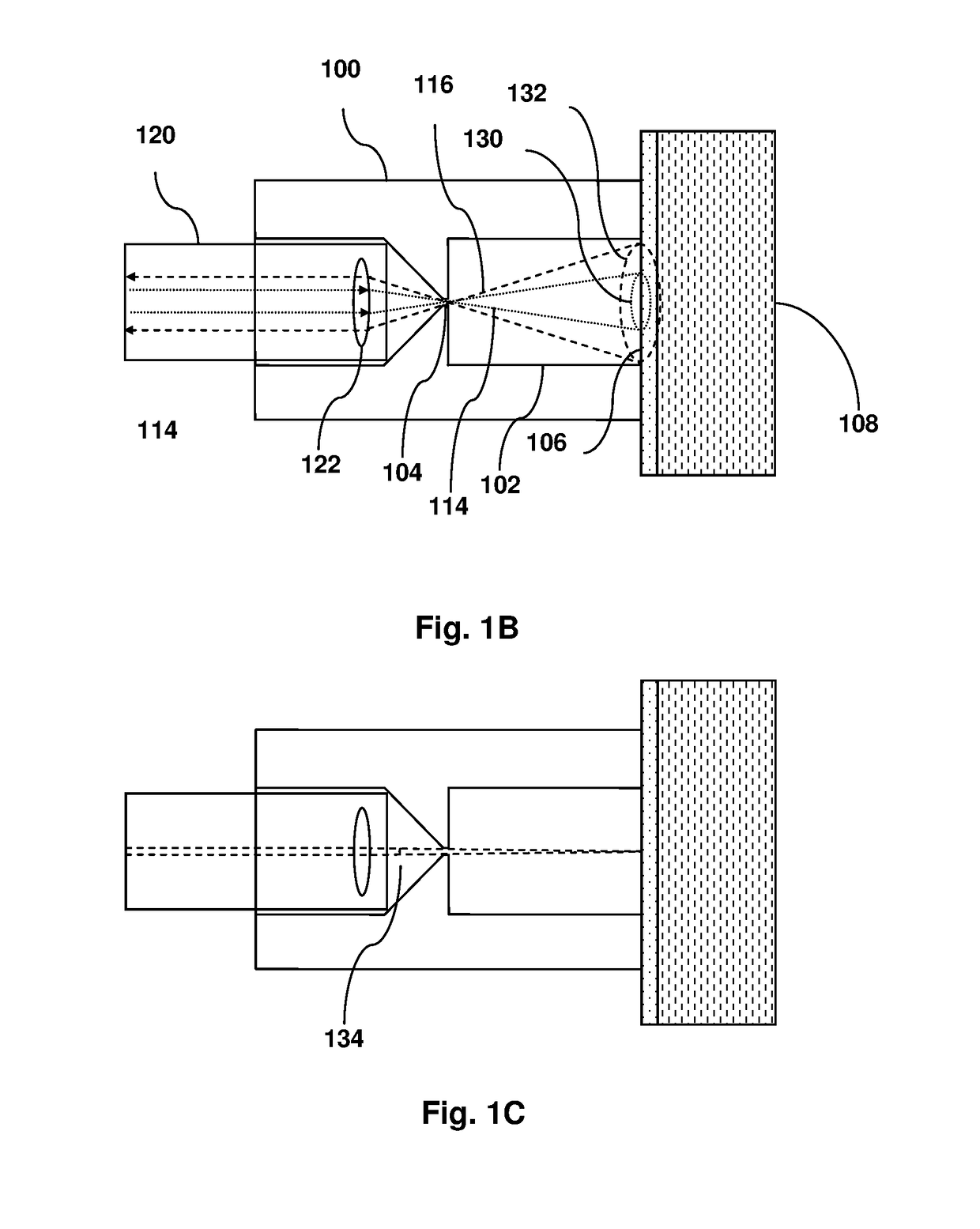
This invention relates to a light delivery and collection device for measuring Raman scattering from a large area of a sample. The light delivery and collection device comprises a reflective cavity made of a material or having a surface coating with high reflectivity to the excitation light and the Raman scattered light. The reflective cavity has two apertures. The first aperture is configured to receive the excitation light which then projects onto the second aperture. The second aperture is configured to be applied close to the sample such that the reflective cavity substantially forms an enclosure covering a large area of the sample. The excitation light produces Raman scattered light from the covered area of the sample. The reflective cavity reflects any excitation light and Raman light scattered from the sample unless the excitation light and the Raman scattered light either emit from the first aperture to be measured with a spectrometer device, or are re-scattered by the sample at the second aperture. The multi-reflection of the reflective cavity greatly improves the excitation efficiency of Raman scattering from the sample and in the meantime enhances its collection efficiency. In addition, it also causes more excitation light to penetrate into a diffusely scattering sample and allows efficient collection of the Raman scattered light generated thereof, hence enabling sub-surface Raman scattering measurement.

Description

FIELD OF THE INVENTION[0001]This invention generally relates to a light delivery and collection device, and more specifically to a light delivery and collection device for measuring Raman scattering of a sample.BACKGROUND[0002]Raman spectroscopy is an optical spectroscopy technique, which measures the inelastic scattering, i.e. Raman scattering of monochromatic light by a material to produce a spectrum characteristic of the material. Raman spectroscopy has been demonstrated to be a powerful non-invasive analytical technology for material characterization and identification.[0003]Conventional Raman spectroscopy generally utilizes a well-focused laser beam to produce Raman scattering signal from the sample. This approach has the apparent advantage of relatively high efficiency in Raman signal excitation and collection. However, it also suffers from the following drawbacks. First, only a small volume of the sample is measured. Thus the collected Raman spectrum may not be very represent...

Claims


Application Information

Patent Timeline
Patent Type & Authority Patents(United States)
IPC IPC(8): G01N21/65G01N21/49
CPCG01N21/65G01N21/49G01N2201/08G01N2201/065G01N2021/651
Inventor ZHAO, JUNZHOU, XIN J.
Owner METROHM SPECTRO INC
Learn More