Wind turbine

US20110254283A1Active Publication Date: 2011-10-20VESTAS WIND SYST AS

Image

  • Wind turbine
  • Wind turbine
  • Wind turbine

Examples


Embodiment Construction

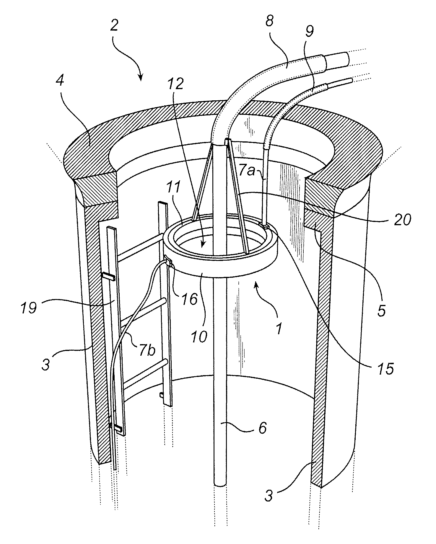
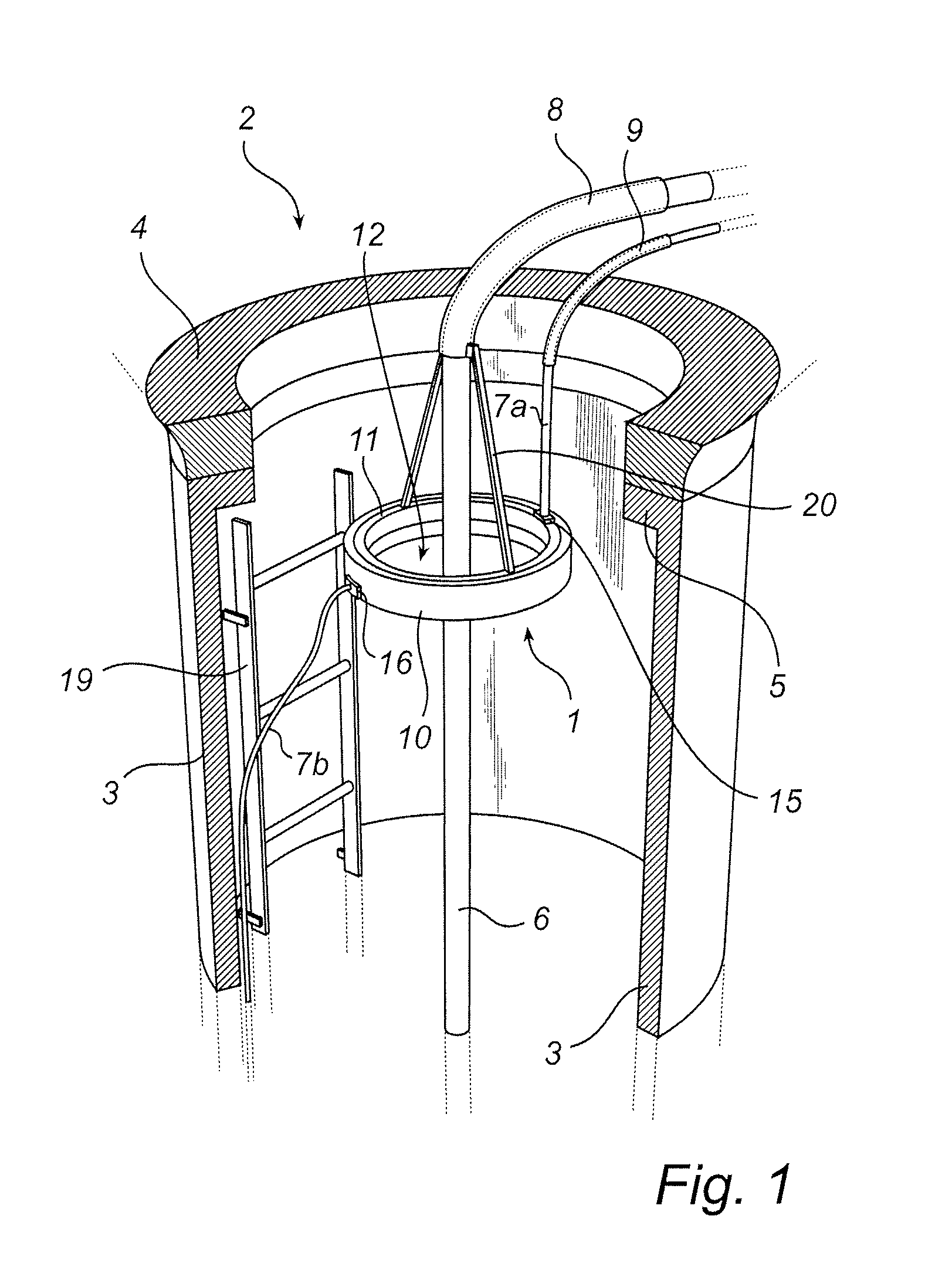
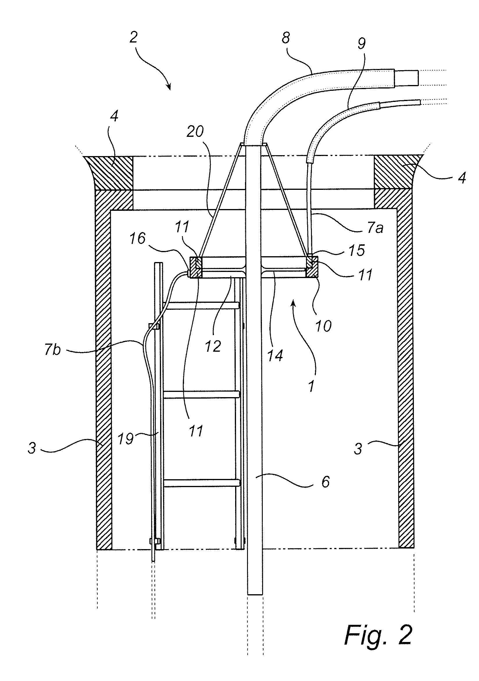
[0036]With reference to FIGS. 1 and 2, a slip ring assembly 1 used in a wind turbine 2 will be described. The wind turbine 2 comprises a tower 3, a nacelle 4 arranged on top of the tower 3 and a slip ring assembly 1. The slip ring assembly 1 is arranged in an upper section of the wind turbine tower 3, adjacent a top flange 5 of the tower 3. The tower 3 is extending from the ground to the nacelle 4. Bearings (not shown) may be arranged between the tower 3 and the nacelle 4, thereby allowing turning of the nacelle 4 in view of the tower 3. A first cable 6, which may be a high voltage cable or the like, is extending from the nacelle 4 towards the ground through the interior of the tower 3 in a vertical direction. At least one second cable 7a, 7b is also extending from the nacelle 4 towards the ground in the vertical direction. The at least one second cable 7a, 7b may be a signal cable, or any other cable arranged in the tower 3.

[0037]In order to facilitate the understanding of the inve...


PUM


Abstract

The present invention relates to a wind turbine (2) comprising a tower (3), a nacelle (4) arranged on top of said tower (3) and a slip ring assembly (1) having at least one slip ring (11), wherein a first cable (6) is extending from the nacelle (4) to the tower (3) via an interior bore (12) of the slip ring assembly (1), and at least one second cable (7a, 7b) is extending from the nacelle (4) to the tower (3) via said at least one slip ring (11), whereby a shielding distance is formed between an outer periphery of said first cable (6) and an inner circumference of said at least one slip ring (11). The present invention further relates to use of a slip ring assembly (1) comprising at least one slip ring (11) for shielding cables (6, 7a, 7b) in a wind turbine (2).

Description

TECHNICAL FIELD[0001]The present invention generally relates to a wind turbine comprising a tower, a nacelle and a slip ring assembly having at least one slip ring. A first cable is extending via an interior bore of the slip ring assembly and at least one second cable is extending via said at least one slip ring. A shielding distance is formed between an outer periphery of said first cable and an inner circumference of said at least one slip ring. The present invention further relates to use of a slip ring assembly comprising at least one slip ring for shielding cables in a wind turbine.BACKGROUND OF THE INVENTION[0002]A wind turbine generally comprises a tower, a nacelle, at least one blade and a yaw bearing arranged between the tower and the nacelle. A high voltage cable is drawn from a generator arranged in the nacelle, down to the ground through the interior space of the tower. Generally, the cable has a diameter of 60-110 mm. This high voltage cable is not the only cable extend...

Claims


Application Information

Patent Timeline
20 Oct 2011
Publication
US20110254283A1
IPC
F03D9/00; F03D11/00
CPC
F03D11/00; Y02E10/726; Y02E10/722; F03D11/0066; F03D80/00; F03D80/85; Y02E10/72
Inventors
OLLGAARD, BORGE