
Control of a brushless motor

Active Publication Date: 2011-10-20
DYSON TECH LTD
View PDF8 Cites 25 Cited by
  • Summary
  • Abstract
  • Description
  • Claims
  • Application Information

AI Technical Summary

Benefits of technology

[0006]On reaching the threshold the method performs one of two processes. In the first process, the winding is immediately freewheeled. In the second process, the winding continues to be excited for an overrun period, after which the winding is freewheeled. By freewheeling the winding, the magnetic flux density in the motor may be better controlled. In particular, magnetic saturation may be avoided.
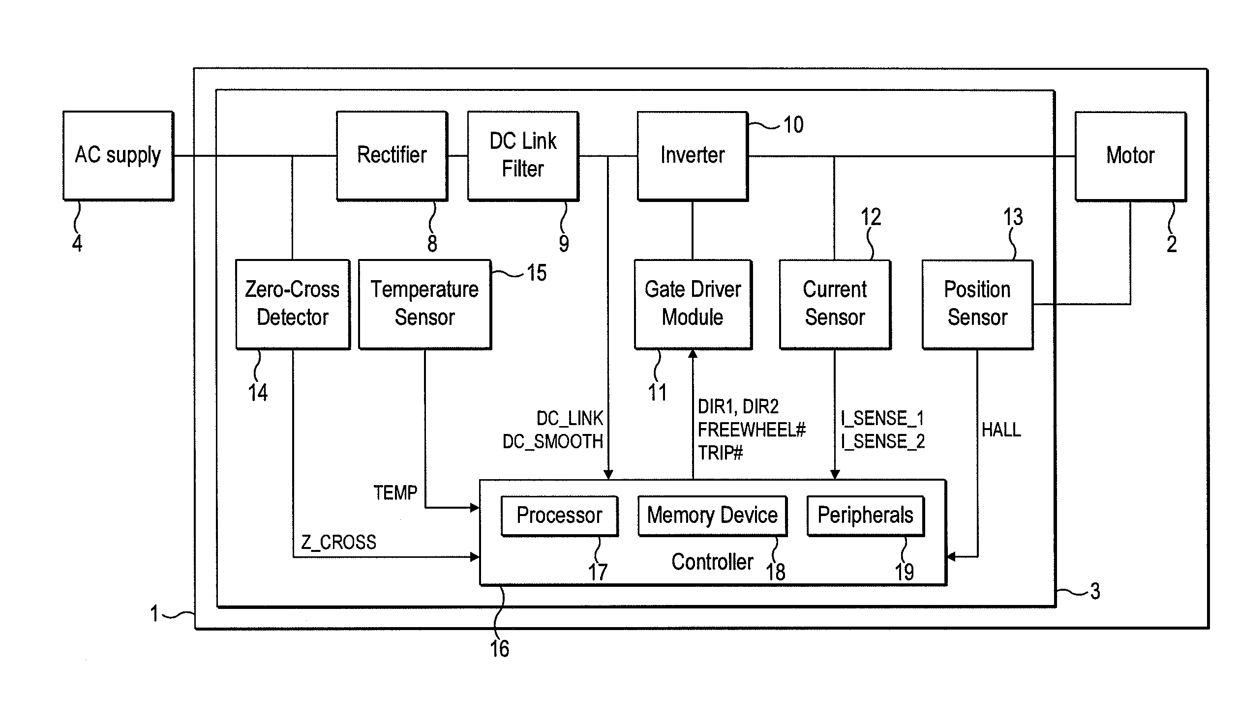
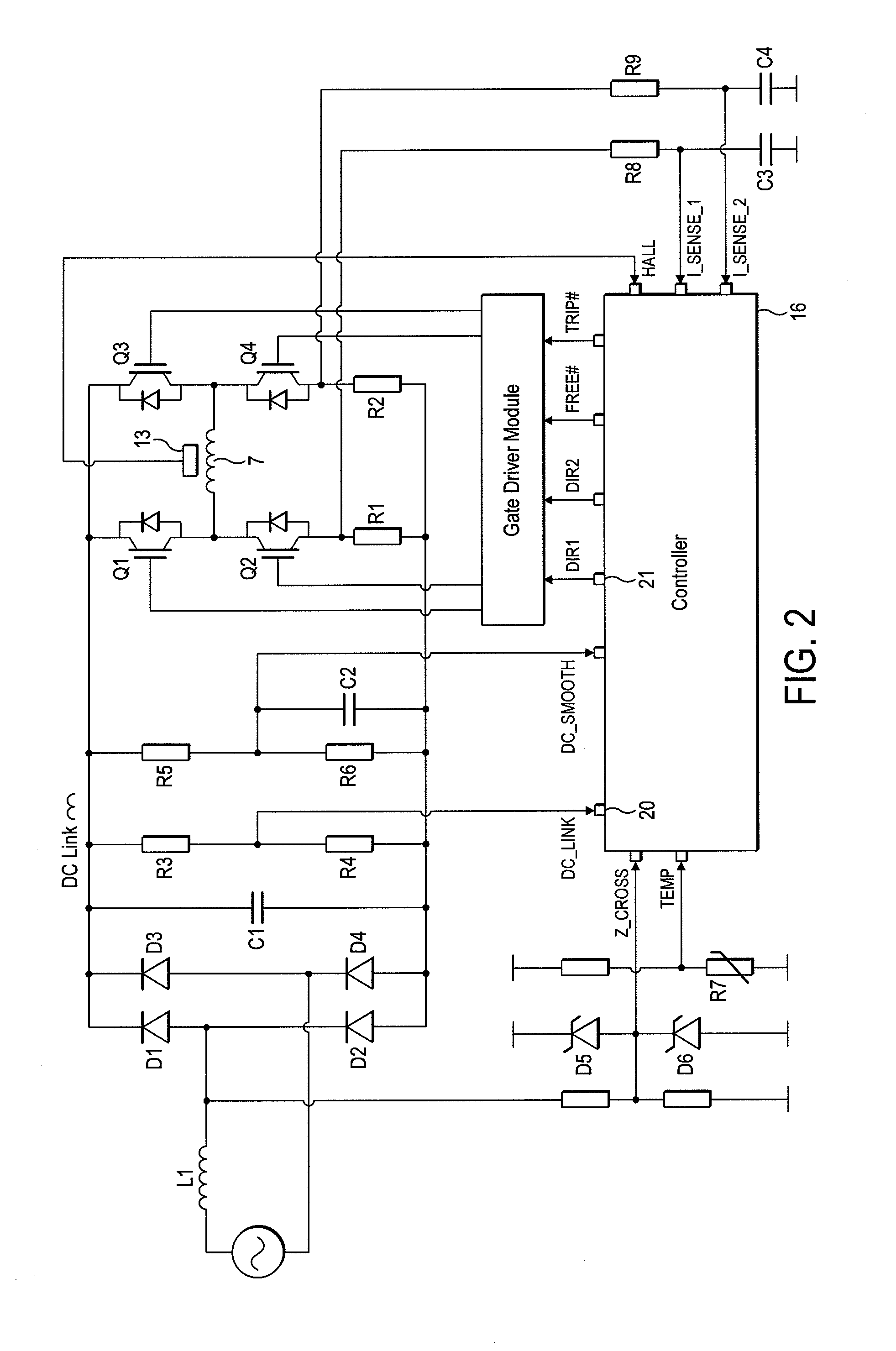
[0020]The motor therefore comprises a permanent-magnet rotor, which induces a back EMF in the winding of the motor. The back EMF makes it difficult to accurately control the amount of current drawn from the power supply. Consequently, conventional permanent-magnet motors typically include an active PFC circuit that outputs a regular DC voltage for use in exciting the winding while ensuring that current drawn from the power supply is substantially sinusoidal. With the motor system of the present invention, on the other hand, the winding is excited until current in the winding exceeds a threshold that is proportional to the rectified voltage. As a result, a waveform approaching that of a sinusoid may be achieved for current drawn from the power supply. Consequently, a motor system having a relatively high power factor may be achieved without the need for a PFC circuit or high-capacitance link capacitor.

Problems solved by technology

However, an active PFC circuit significantly increases the cost of the control system.
Additionally, the PFC circuit requires a high-capacitance DC link capacitor, which is both physically large and expensive, in order to provide a regular feedback voltage to the PFC circuit.

Method used


Image

  • Control of a brushless motor
  • Control of a brushless motor
  • Control of a brushless motor

Examples


specific example

[0241]A particular embodiment of the motor system 1 will now be described by way of example only. Values for various hardware components of the motor system 1 are detailed in FIG. 19, while FIG. 20 lists various constants and thresholds employed by the controller 16. FIGS. 21 and 22 detail the flux-linkage characteristics of the link inductor L1 and the motor 2.

[0242]As illustrated in FIG. 23, the motor system 1 has seven modes of operation: Fault, Initialization, Stationary, Low-Speed Acceleration, Mid-Speed Acceleration, High-Speed Acceleration, and Running. Accordingly, in comparison to that previously described and illustrated in FIG. 8, the motor system 1 has one additional mode of operation.

[0243]Fault, Initialization, Stationary and Low-Speed Acceleration Modes are unchanged from that previously described. Mid-Speed Acceleration Mode corresponds to the previously-described High-Speed Acceleration Mode. Consequently, when operating in Mid-Speed Acceleration Mode, the controlle...


PUM


Abstract

A method of controlling a brushless motor that includes rectifying an alternating voltage to provide a rectified voltage having a ripple of at least 50%, exciting a winding of the motor with the rectified voltage, and performing a first process or a second process in response to current in the winding exceeding a threshold that is proportional to the rectified voltage. The first process includes freewheeling the winding, while the second process includes continuing to excite the winding for an overrun period and freewheeling the winding at the end of the overrun period. Additionally, a control system that implements the method, and a motor system that incorporates the control system.

Description

REFERENCE TO RELATED APPLICATIONS[0001]This application claims the priority of United Kingdom Application No. 1006395.6, filed Apr. 16, 2010, the entire contents of which are incorporated herein by reference.FIELD OF THE INVENTION[0002]The present invention relates to control of a brushless motor.BACKGROUND OF THE INVENTION[0003]A brushless motor typically includes a control system for controlling the excitation of phase windings of the motor. When driven by an AC supply, the control system often includes an active power factor correction (PFC) circuit, which outputs a regular DC voltage for use in exciting the phase windings while ensuring that current drawn from the AC supply is substantially sinusoidal. As a result, a relatively high power factor may be achieved. However, an active PFC circuit significantly increases the cost of the control system. Additionally, the PFC circuit requires a high-capacitance DC link capacitor, which is both physically large and expensive, in order t...

Claims


Application Information

Patent Timeline
IPC IPC(8): H02P6/14
CPCH02P6/008H02P6/085H02P2209/07H02P6/181H02P6/142H02P6/26H02P6/15Y10S388/9072
Inventor CLOTHIER, ANDREW CHARLTONGREETHAM, STEPHENTUFTNELL, NICHOLAS DALIBOR
Owner DYSON TECH LTD
Learn More