
High speed barrel polishing device

a barrel and polishing technology, applied in the direction of edge grinding machines, grinding machine components, manufacturing tools, etc., can solve the problems of long polishing process, large mechanical workpieces, devices used to polish multi-layer electronic components, etc., and achieve the effect of less damage and higher speed

Inactive Publication Date: 2011-10-20
IBM CORP
View PDF13 Cites 10 Cited by
  • Summary
  • Abstract
  • Description
  • Claims
  • Application Information

AI Technical Summary

Benefits of technology

[0008]One aspect of the present invention includes providing a high speed vertical barrel polishing device and high speed polishing containers that may be used for barrel polishing in a variety of applications, such as a multi-layer electronic component manufacturing process. Specifically, various embodiments of the presently described polishing device are capable of rotating a set of one or more containers around a generally vertical axis with higher speeds and less damage than provided by barreling techniques around a generally horizontal axis.
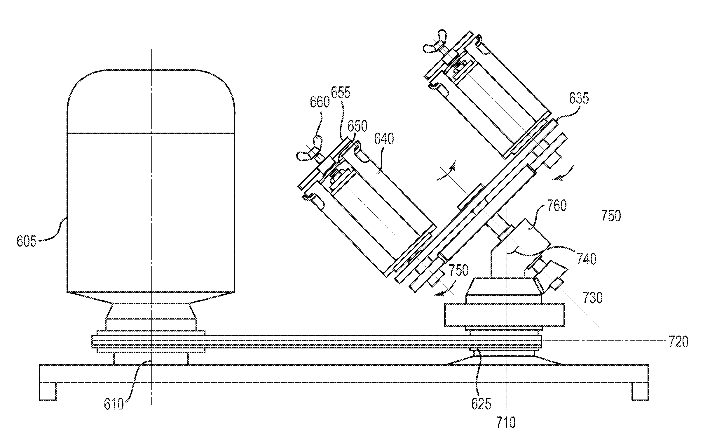
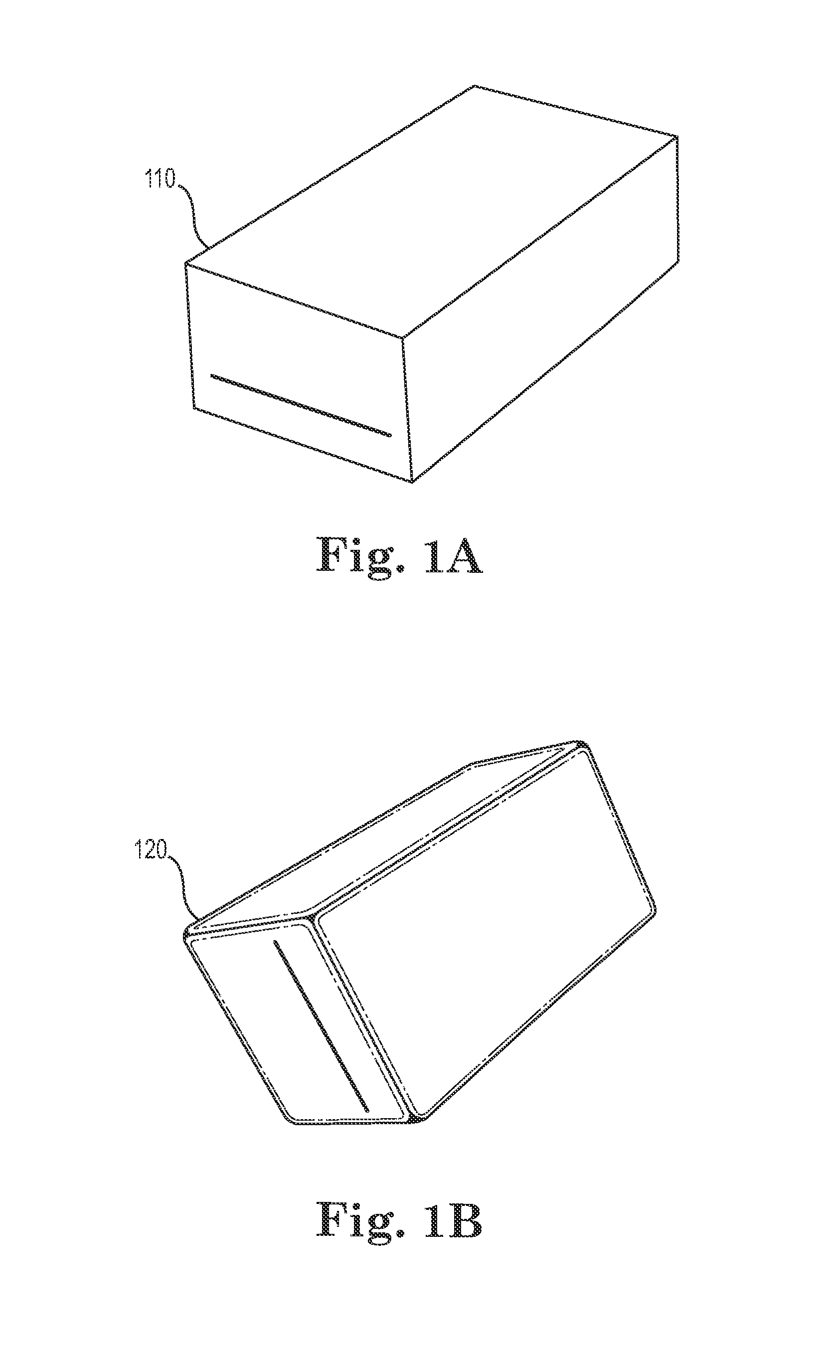
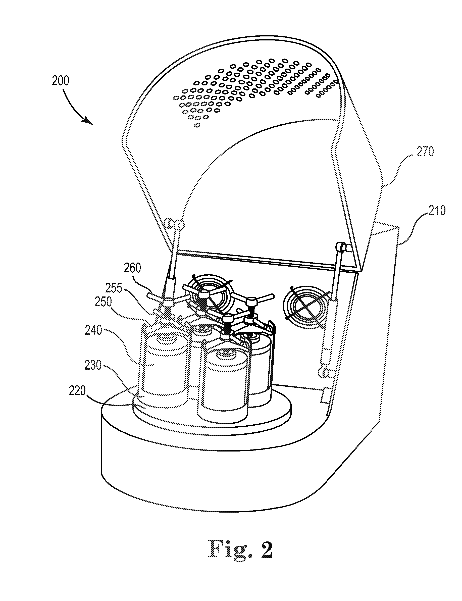
[0009]In one embodiment, polishing containers (also referred to in the art as “canisters”, “jars”, or “pots”) are adapted for use within a generally vertically rotating barrel polishing device, such as a planetary ball mill. The polishing containers are then rotated at high speed to polish items placed inside such as multi-layer electronic components. Whereas typical polishing containers in a straight, vertical cylinder shape may fail to polish all components placed within the container, the interior shape of the container provided by one embodiment of the present invention enables improved agitation and circulation and therefore improved polishing capabilities. In one embodiment, the internal cavity of the container is defined by an inner bottom with gradually sloped upward edges to enable components to fly up during the rotation of the container. The diameter of the internal cavity is larger within its central section, while becoming gradually smaller towards both of the top and bottom of the container. In a further embodiment, the internal cavity also contains a substantially flat bottom surface in order to keep the container stable during high-speed rotation.
[0010]As suggested, in one embodiment of the present invention, a vertical planetary ball mill may be adapted for use with a set of containers having this modified internal cavity structure. The vertical planetary ball mill therefore can simultaneously operate a number of vertically rotating polishing containers, each filled with the same or different components. Further, the containers of the vertical planetary ball mill can be configured to operate with a hermetic, watertight sealed construction. Therefore, the containers may be filled and successfully operated at high speed with a number of varying wet and dry materials, such as dry polishing media, abrasives, and various types of liquids.
[0011]A further embodiment of the present invention provides for operation of a vertical planetary ball mill that rotates the polishing containers at a tilted angle around a set of tilted axes. The tilted axes that the containers and the revolution plate revolve about are not parallel to (i.e., are different from) the axis extending through a support member or other fixed vertical reference point. The angle between the support member and the tilted axis is generally referred to herein as the “tilted angle” of operation. In one embodiment the tilted angle is a substantially 45 degree angle, thereby allowing typical operation in a midpoint between entirely horizontal and vertical positions. Rotation around a tilted axis between horizontal and vertical positions further decreases accumulation of components at the bottom of the container and increases relative movements within the container during polishing. Further, rotation around the tilted axis reduces collision forces that would otherwise occur during a horizontally-oriented barrel polishing process.
[0013]In further embodiments, this gradual transition between the first end and the second end of the container interior cavity includes a first transition between the first end and a central widest point existing between the first end and the second end, and a second transition in an opposite direction of the first transition between the central widest point and the second end. This provides a generally curved interior structure between the first end and second end without any corners or crevices for components to encounter during polishing. This central widest point is not necessarily an equal distance between the first and second ends, but rather may be located either closer to the first or second ends. In still another embodiment, the first end (e.g., bottom) of the interior cavity is defined by a substantially flat surface to promote high-speed rotational stability of the container.

Problems solved by technology

There are many limitations of existing polishing devices when used for polishing multi-layer electronic components.
Horizontal barrel devices must be operated at low speed in order to prevent damage to components, which results in a long polishing process.
Other types of devices that are used to polish large mechanical workpieces, printed circuit boards, or semiconductor wafers generally cannot be used with small, multi-layer components.
Many of these polishing devices often result in uneven polishing or damage to multi-layer electronic components.
Conventional horizontal-type barrel finishing systems are big and heavy, relatively inefficient, and do not provide polishing speed as fast as vertically oriented barrel finishing systems.
This results in a longer floor to floor time for the overall manufacturing process.
Horizontal barrel polishing techniques may also cause severe collisions due to the combination of gravity, revolution centrifugal force, and rotation centrifugal force.
Some vertical barrel finishing devices exist in the art but have not been effectively adapted for use in electronic component polishing.
When vertical planetary ball mills are used for barrel polishing, however, all of the components will fail to properly circulate within the barrel which results in incomplete polishing batches.

Method used


Image

  • High speed barrel polishing device
  • High speed barrel polishing device
  • High speed barrel polishing device

Examples


Embodiment Construction

[0029]The present invention provides improved polishing devices and techniques useful during a generally vertically-oriented barrel polishing process. The presently disclosed high speed barrel polishing apparatus and modified barrel polishing container is particularly useful for polishing a large number of components, such as hundreds or thousands of small electronic components, in a relatively rapid fashion.

[0030]Some of the other advantages of the various embodiments of the present invention include providing uniform polishing, higher speed, and the use of low cost equipment. Existing vertical planetary ball mill machines may be adapted to provide vertical polishing capabilities in a relatively small space with a small number of modifications. Other advantages of the various embodiments of the present invention include providing a barrel polishing techniques which expose the polished components to less gravitational forces and collisions, thus resulting in reduced cracking and dam...


PUM

PropertyMeasurementUnit
Angleaaaaaaaaaa
Timeaaaaaaaaaa
Angleaaaaaaaaaa

Abstract

A high speed polishing device useful for polishing a large number of miniature components, such as multi-layer electronic components, is disclosed. In various embodiments of the present invention, a vertical planetary ball mill or other barrel polishing device is modified to rotate polishing containers having a modified interior cavity structure. This interior cavity provides a smooth, gradually curved interior sidewall that improves circulation within the container during high-speed vertical polishing rotation. The improved circulation results in polishing for a larger number of components placed within the container and in less time than existing polishing container structures. In further embodiments, the containers are rotated around a generally tilted axis positioned at an angle between entirely vertical and horizontal positions. Rotation about a tilted axis further reduces collisions and increases relative polishing movement within the container.

Description

CROSS REFERENCE TO RELATED APPLICATIONS[0001]This application claims priority to Chinese patent application number 201010153032.7, filed Apr. 19, 2010, the content of which is hereby incorporated by reference in its entirety.FIELD OF THE INVENTION[0002]The present invention generally relates to mechanical polishing devices. The present invention more specifically relates to a polishing device useful for polishing a plurality of components such as a batch of multi-layer electronic components.BACKGROUND OF THE INVENTION[0003]Barrel polishing is a common step performed during the manufacturing process of multi-layer electronic components, for components such as inductors, beads, capacitors, and oscillators. Polishing is necessary in order to round the corners and remove sharp edges from these components. Current polishing processes typically place a large number of components inside of a horizontal, rotating barrel, and expose the components to an abrasive that slowly polishes the edge...

Claims


Application Information

Patent Timeline
IPC IPC(8): B24B31/033B24B1/00B24B31/12
CPCB24B31/0218B24B31/033B24B31/023
Inventor MA, YUANFENGWU, LINLANGZHANG, SHENG
Owner IBM CORP
Learn More