
Utilization of tracers in hydrocarbon wells

a technology of hydrocarbon wells and tracers, which is applied in the field of hydrocarbon production, can solve the problems of unwelcome use of radioisotopes as tracers, and the likelihood of significant time delay between taking samples, so as to reduce the possibility of human error in collecting and the effect of rapid availability of results

Inactive Publication Date: 2011-10-20
SCHLUMBERGER TECH CORP
View PDF14 Cites 59 Cited by
  • Summary
  • Abstract
  • Description
  • Claims
  • Application Information

AI Technical Summary

Benefits of technology

[0015]Analysis of samples is preferably carried out at, or in the vicinity of, the location where samples are taken. Analysis may be carried out at the same place as the taking of samples, or analysis may be carried out nearby, such as within 5 Km, better within 2 Km of the location where samples are taken. Sampling and analysis may both be carried out at or near a location from which the well is controlled. This has the advantage that the results of the analysis can become available quickly, so that the information obtained can be used in well control.
[0016]Sampling flow, as this invention requires, has advantages compared to examining the entire flow for a physical property characteristic of the presence of tracers, especially when the tracer is not radioactive. Analyzing the entire flow is necessarily confined to analytical techniques which do not harm the material flowing from the well and these are generally tests for a physical property. A sensor for a physical property other than radioactivity, such as a detector for fluorescence, needs to be exposed to the flow in pipework and so become exposed to anything which deposits on the interior of the pipework, for example scale or asphaltene. A thin coating, which would be tolerable on pipework, can interfere with operation of the sensor. Keeping the sensor operational then becomes problematic, potentially requiring the main flow to be shut off in order to carry out maintenance work such as cleaning sensors or to replace a failed sensor. By contrast, if samples are taken from the flow and then tested, the testing equipment can be operated and maintained without interfering with the main flow from the well, even if the testing method is the same.
[0017]Sampling the flow and analysis of samples, rather than analyzing the full flow for a physical property, gives greater choice of analytical technique, permitting the use of analytical methods which cannot be applied to a large and moving quantity of material.
[0018]Sampling also has the benefit that a portion of the sample can be tested while another portion is retained for a repeat test, if that should be required, or for further, more extensive testing, in the event that an initial test for the presence of tracer gives a positive result. It also provides the option of testing part of the sample at the wellsite, with the advantage of rapid availability of results, while also retaining the possibility to send another part of the sample elsewhere for further analysis if that is called for by analytical results obtained at the well site.
[0019]Automated sampling has the benefit that it can provide samples taken at regular intervals while mitigating the possibility of human error in collecting the samples. Carrying out an analysis close to the well site is advantageous in conjunction with automated sampling, because automated sampling facilitates and indeed encourages taking a plentiful number of samples, which can be beneficial, while analysis on site avoids the need to ship a large number of samples to a remote laboratory. A combination of repeated automatic sampling and analysis of samples at the well site can provide a succession of results in something approaching real time.
[0043]More specifically, fluorescent tracers may be used. These are detectable by stimulating fluorescence with ultra-violet or visible light and observing the spectrum of emitted light. As mentioned above this technique has been proposed for examination of the entire flow from a well, but applying it to samples rather than the whole flow has the benefit that equipment maintenance does not interrupt production.

Problems solved by technology

The use of radioisotopes as tracers is often unwelcome because of safety issues and regulations controlling the handling of radioactive material.
Because of the distance between the well site and the laboratory, there is apt to be a significant time delay between taking the sample and obtaining an analysis of tracer(s) within it.

Method used


Image

  • Utilization of tracers in hydrocarbon wells
  • Utilization of tracers in hydrocarbon wells
  • Utilization of tracers in hydrocarbon wells

Examples


Embodiment Construction

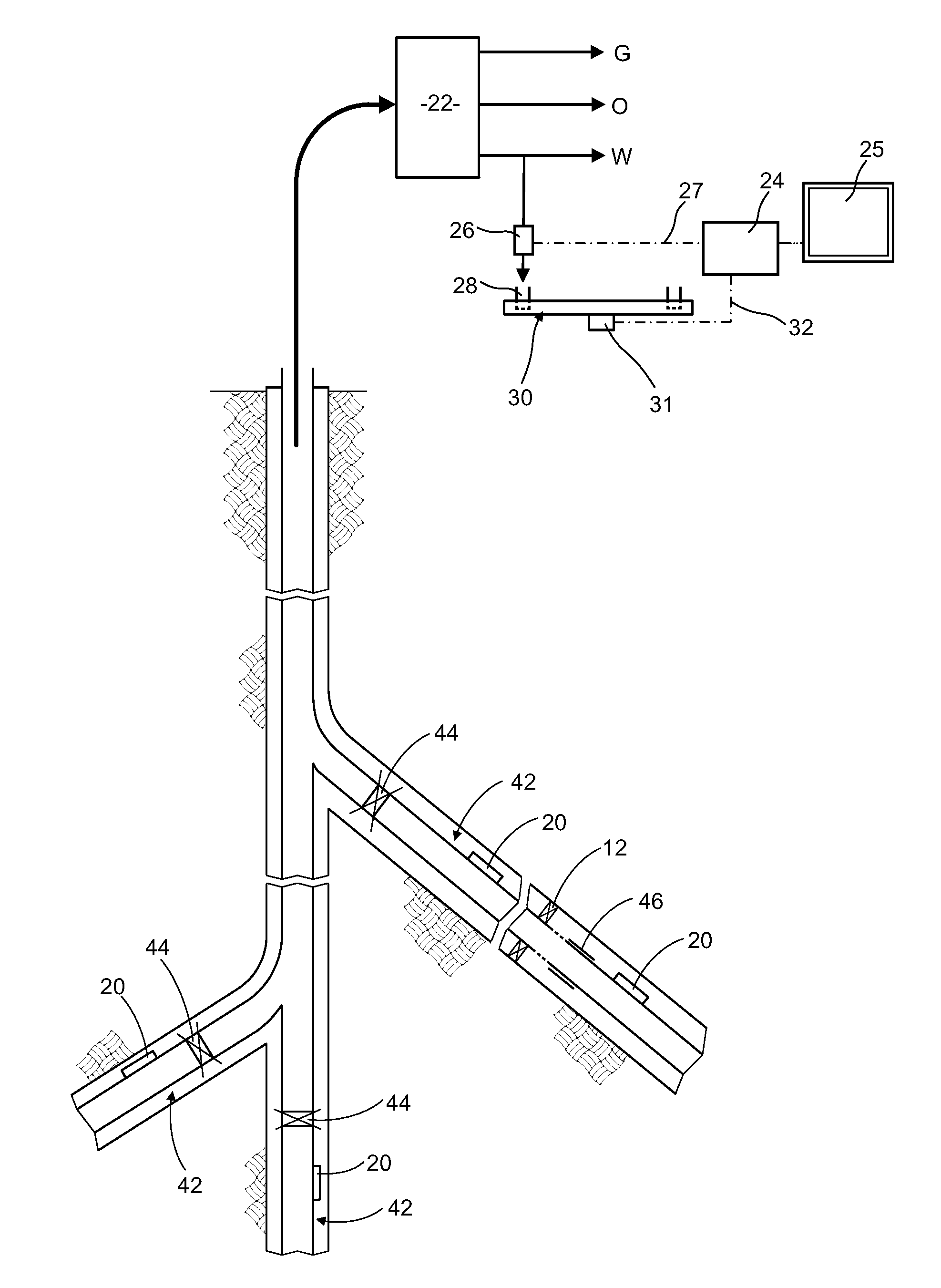
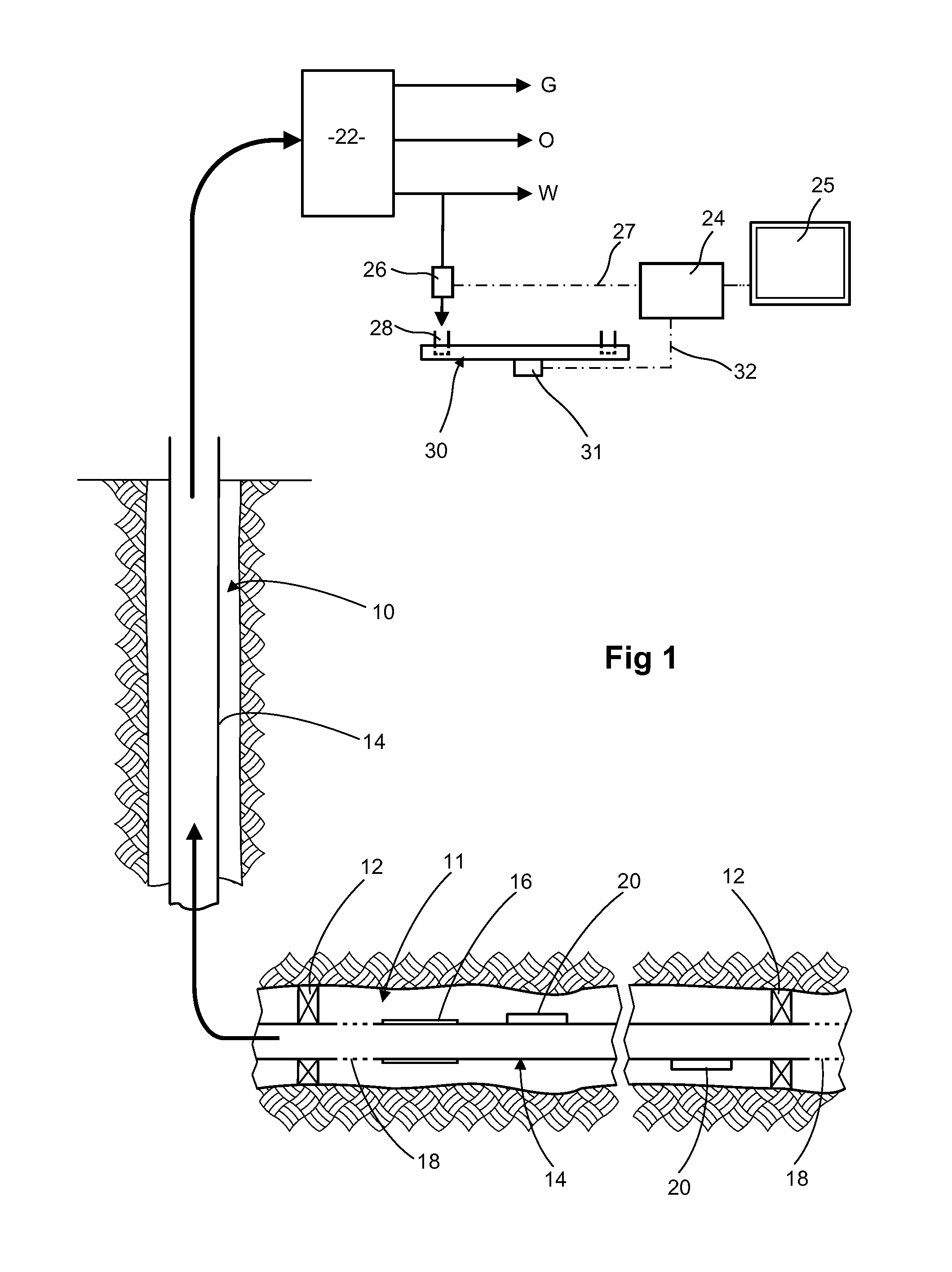
[0062]FIG. 1 diagrammatically illustrates a well 10 with a long lateral 11 which is subdivided into sections by packers 12 around the production tube 14. One section between two packers 12 is shown in the lower part of FIG. 1. Within each section there is a valve arrangement which controls entry to the production tube 14. Such a valve arrangement can be of conventional construction. As an example the arrangement shown in FIG. 1 comprises a sliding sleeve 16 which can be moved in response to a command transmitted from the surface so as to cover and close openings 18 for entry of fluid into the production tube 14.

[0063]Blocks of material 20 are secured to the exterior of the production tube 14 at each end of this section of the lateral. This material 20 encloses a tracer. Both blocks in this section contain the same tracer, but a different tracer is used in each section. The material of the blocks is such that the tracer is not released if the material 20 is exposed to oil but is rele...


PUM


Abstract

Monitoring of a wellbore which penetrates a reservoir is carried out by providing tracer material at one or more subterranean locations within or proximate the wellbore, so that tracer may enter the flow and be present in flow from the wellbore; repeatedly taking samples from the flow from the wellbore, and analyzing the samples for the presence of tracer, in the vicinity of the wellsite. Taking samples from the flow will generally be done at the surface and may be done by automatic equipment controlled by a programmed computer. The computer may be programmed to take action, such as operating a valve within the well, in response to detection of tracer. Sampling repeatedly and analyzing on site can provide information in something close to real time and thus integrates the use of tracers into an overall process of monitoring and control.

Description

FIELD OF THE INVENTION[0001]This invention relates to the utilization of tracers in connection with hydrocarbon production and especially in connection with monitoring a wellbore penetrating a hydrocarbon reservoir.BACKGROUND OF THE INVENTION[0002]The term tracer has generally been used to denote a material which is deliberately introduced into fluid flow which is taking place. Detection of the tracer(s) downstream of the injection point(s) provides information about the reservoir or about the wellbore penetrating the reservoir. In particular, deliberate addition of tracers has largely been used to observe flow paths and transit times between injection wells (used for instance to inject a water flood into a reservoir) and production wells. For this application of tracers to study inter-well flow, the tracer materials have generally been dissolved in the injection water at the surface before it is pumped down the injection well. As reported by Guan et al. (Journal of Canadian Petrole...

Claims


Application Information

Patent Timeline
IPC IPC(8): E21B49/00G01V9/00G06F19/00
CPCE21B47/1015E21B47/11
Inventor COOPER, IAINMILLER, MATTHEWVIDICK, BENOITTUSTIN, GARY
Owner SCHLUMBERGER TECH CORP
Learn More