
Metallic tower

a technology of metal towers and towers, applied in the direction of towers, buildings, buildings types, etc., to achieve the effects of optimizing gyration radius, reducing channel sections, and reducing webs

Active Publication Date: 2011-11-03
SECCIONAL BRASIL SA
View PDF8 Cites 9 Cited by
  • Summary
  • Abstract
  • Description
  • Claims
  • Application Information

AI Technical Summary

Benefits of technology

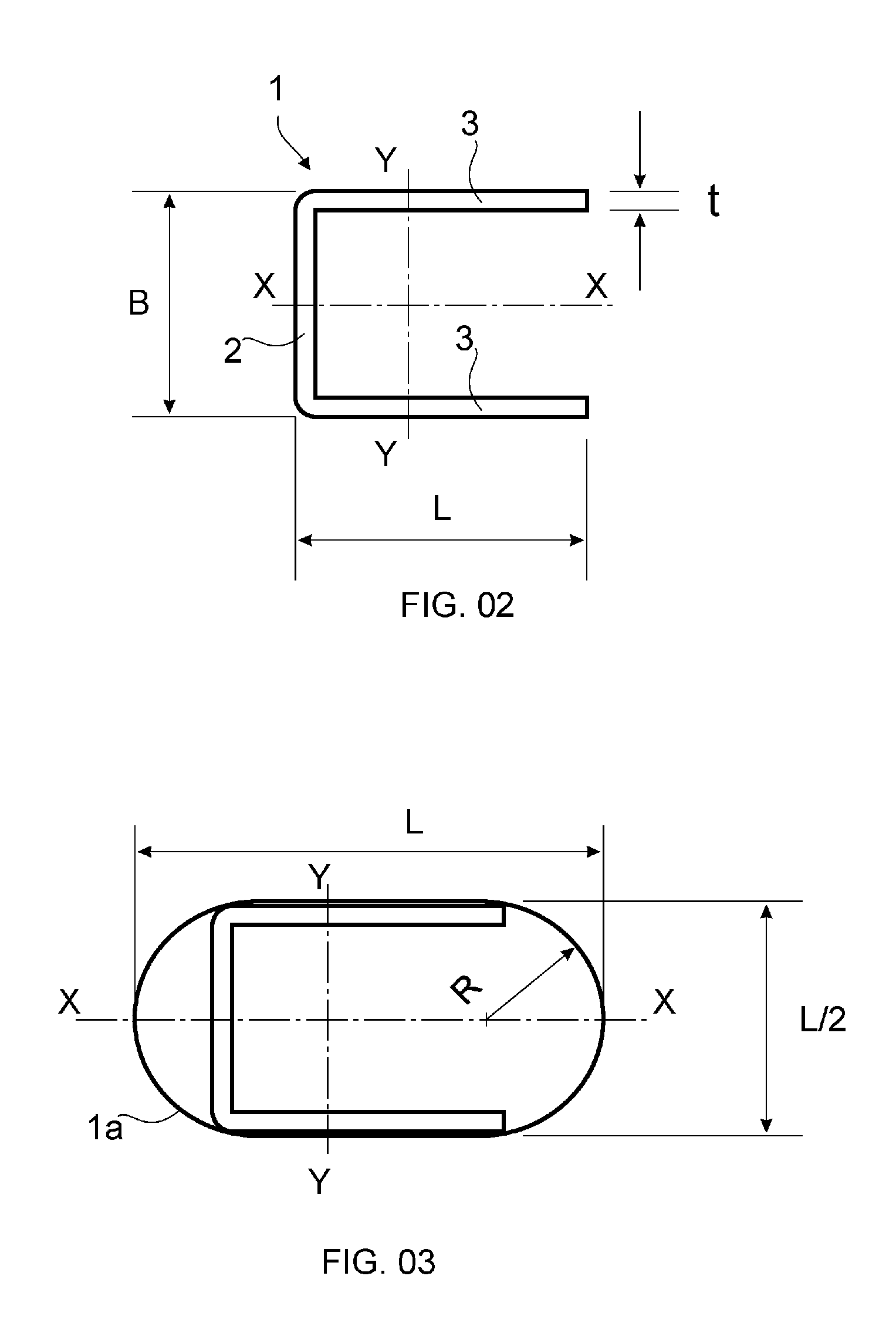
[0014]The present invention has several advantages over the prior art. By adopting truss members with reduced channel section with reduced web, it is obtained optimized gyration radius in all axis directions, reduced section area facing the wind and lower drag coefficients. Therefore, due to the improvement in the aerodynamic and structural performance and behavior it is obtained a surprising reduction in the total weight of the structure, beside the reduction of the loads over the basement. This surprising effects are obtained even using the same silhouette of a prior art truss tower. Consequently, even for the same silhouette, a significantly more economical tower is obtained. Nevertheless, with the re-adequation of the silhouette design to the new aerodynamic and structural forces, the advantages of the present invention become even more significant. Moreover, the possibility of unrolling the metal sheets in automated machines for cutting, bending and perforating, allows significant manufacturing productivity gains, including the elimination of scrap.

Problems solved by technology

Nevertheless, due to structural design and cost constraints, it is very common the use metallic lattice towers in high voltage electric power transmission and telecommunications applications.

Method used


Image

  • Metallic tower
  • Metallic tower
  • Metallic tower

Examples


Embodiment Construction

[0036]This invention is not limited in its application to the details of construction and the arrangement of components set forth in the following description or illustrated in the drawings. The invention is capable of other embodiments and of being practiced or of being carried out in various ways. Also, the phraseology and terminology used herein is for the purpose of description and should not be regarded as limiting. The use of ‘including’, ‘comprising’, ‘having’, ‘containing’ or ‘involving’, and variations thereof herein, is meant to encompass the items listed thereafter and equivalents thereof as well as additional items.

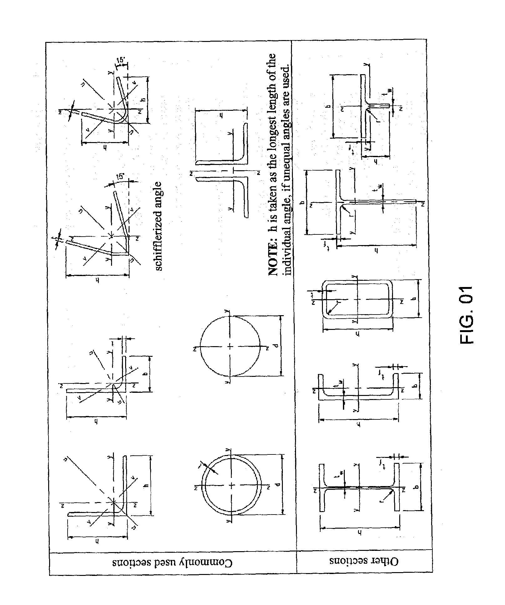
[0037]FIG. 01 is an extraction of the ‘FIG. 1.1.’ of the European Standard prEN 1993-3-1:2004—European Standard prEN 1993-3-1:2004—Eurocode 3: Design of steel structures, Part 3.1.: Towers, masts and chimneys—Towers and masts, which shows the ‘Dimensions and axes of sections’, including ‘Commonly used sections’ and ‘Other sections’. Such common standard sectio...


PUM


Abstract

This invention relates to metallic towers or the like utilized for electric power transmission lines, telecommunications, wind energy generators and other applications. The standard sections used in lattice towers of the prior art have structural and aerodynamic deficiencies. To overcome the drawbacks and problems the prior art one aspect of the present invention is directed to a metallic tower comprising lattice members with a channel section, wherein the length of the channel web is smaller than the length of the channel legs.

Description

TECHNICAL FIELD[0001]This invention relates to metallic towers or the like utilized for electric power transmission lines, telecommunications, wind energy generators and other applications.BACKGROUND ART[0002]Towers or the like utilized for electric power transmission lines, telecommunications, wind energy generators and other applications are well know in the prior art. The structural designs, components and materials of such towers vary depending upon the application. Nevertheless, due to structural design and cost constraints, it is very common the use metallic lattice towers in high voltage electric power transmission and telecommunications applications.[0003]In such lattice towers, the skilled in the art usually adopt the standard sections such as the ones described in the European Standard prEN 1993-3-1:2004—Eurocode 3: Design of steel structures, Part 3.1.: Towers, masts and chimneys—Towers and masts.DISCLOSURE OF INVENTIONTechnical Problem[0004]The standard plane sections us...

Claims


Application Information

Patent Timeline
IPC IPC(8): E04H12/08
CPCE04H12/10Y02E10/728
Inventor DE ABREU, PAULO EMMANUEL
Owner SECCIONAL BRASIL SA
Learn More