Energy recovery system for an internal combustion engine

a technology for energy recovery and internal combustion engines, which is applied in the direction of machines/engines, mechanical equipment, transportation and packaging, etc., can solve the problems of reducing the benefits of the system, requiring space for the heat exchanger arranged in the exhaust gas line, and bringing weight and cost, so as to improve energy recovery, reduce costs, and make the system lighter

Inactive Publication Date: 2011-11-03
RENAULT TRUCKS
View PDF11 Cites 7 Cited by
  • Summary
  • Abstract
  • Description
  • Claims
  • Application Information

AI Technical Summary

Benefits of technology

[0010]In other words, according to an aspect of the invention, a single part serves both as a particulate filter and as a heat exchanger. As a consequence, the system is less bulky than prior art systems in which there is provided a filter and a heat exchanger as two separate parts. Furthermore, the invention makes it possible to make the system lighter and to reduce costs. Moreover, since no separate heat exchanger is provided, there is no added back pressure, contrary to prior art systems.
[0011]The invention, according to an aspect thereof makes it possible to achieve two goals. On the one hand, an aspect of the invention improves energy recovery with respect to prior art systems, because the exhaust gas passes through filtering walls, which enhances thermal exchange. The energy is continuously recovered by the filtering means and then transferred to the heat exchanging means, i.e. to the energy recovery means via the heated fluid flowing in the secondary line.

Problems solved by technology

First of all, the heat exchanger arranged in the exhaust gas line requires space, brings weight and cost, in addition to the generally already existing exhaust gas after-treatment systems (such as particulate filters, selective catalytic reduction devices, etc.).
Moreover, this heat exchanger can generate undesirable side-effects, such as increased backpressure in the exhaust line, which is prejudicial to the global engine efficiency and therefore reduces the benefits of the system.
Indeed, because heat is transferred to the fluid flowing in the secondary line, the risk to harm the filtering means—or possible additional after-treatment devices located downstream from the particulate filter—due to too high temperature is significantly lowered.

Method used


Image

  • Energy recovery system for an internal combustion engine
  • Energy recovery system for an internal combustion engine
  • Energy recovery system for an internal combustion engine

Examples


first embodiment

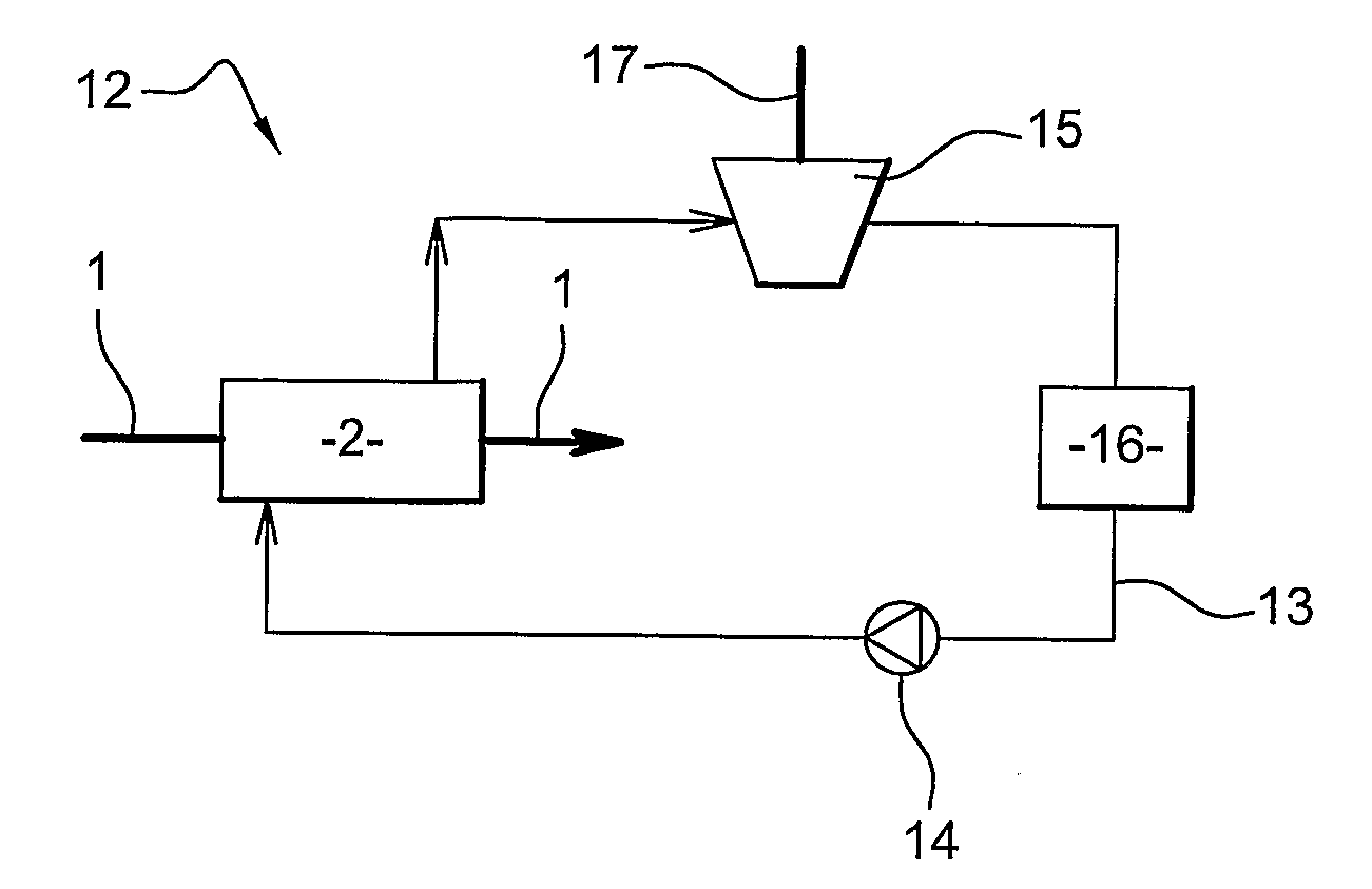
[0043]A first embodiment is illustrated in FIG. 4.

[0044]In this embodiment, the secondary line is a closed loop forming a Rankine thermodynamic cycle.

[0045]Water (or another liquid, such as an organic fluid) is moved by means of a pump 14 in said secondary line 13, and enters the particulate filter 2, in which said water is evaporated into steam (or another corresponding gas), thanks to the heat received from the exhaust gas. Said particulate filter 2 therefore works as an evaporator. The steam going out of said particulate filter 2 is then expanded in a turbine 15 located downstream from said particulate filter 2. The expanded steam is then condensed into water in a condenser 16 located downstream from said turbine 15, said water being again directed towards the particulate filter 2 by means of the pump 14.

second embodiment

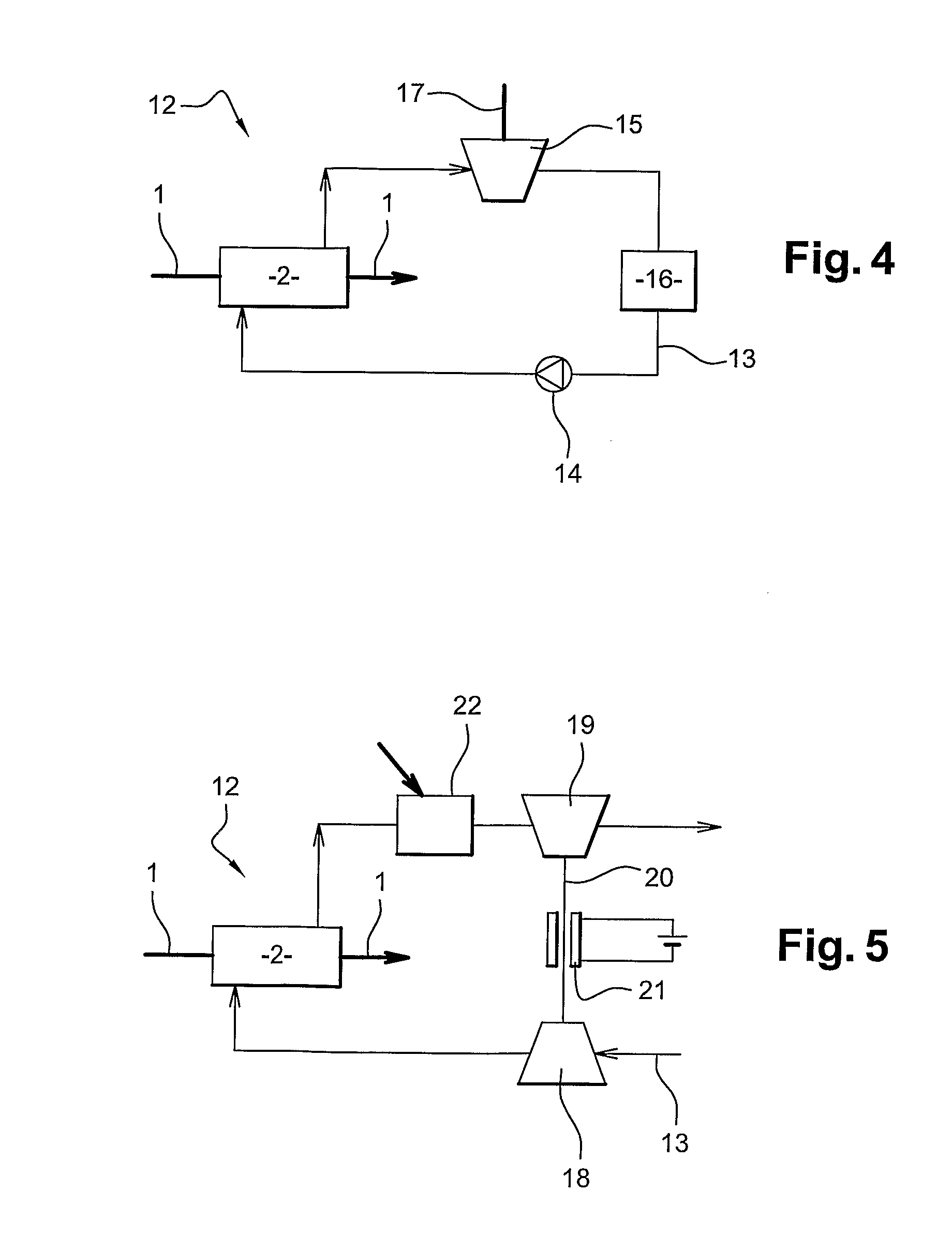
[0046]In this embodiment, the heat of exhaust gases is recovered into work on the turbine shaft 17. A second embodiment is illustrated in FIG. 5.

[0047]In this embodiment, the secondary line is an open loop forming a Brayton thermodynamic cycle. A gas, for example ambient air, is first compressed in a compressor 18 located upstream from said particulate filter 2, then passes through the heat exchanging area 5 of the particulate filter 2 acting as a heat exchanger, where said air is heated by the hot exhaust gases. Downstream from said particulate filter 2, heated air reaches a turbine 19 where it is expanded, thereby transforming the energy conveyed by the air into mechanical energy.

[0048]Turbine 19 is mechanically connected to compressor 18 by means of a shaft 20. The energy produced by the warm air expansion is recovered into mechanical energy on said shaft 20. Said energy is partially used to operate compressor 18.

[0049]The system may further comprise an alternator 21 designed to ...


PUM


Abstract

An energy recovery system includes an exhaust line which is capable of collecting exhaust gas from an exhaust manifold of the engine and which is equipped with a particulate filter, a secondary line which is thermally linked with, but distinct from, the exhaust line, and which carries a fluid. The particulate filter has a filtering part in which exhaust gases can flow and a heat exchanging part in which the fluid can flow, the filtering part and heat exchanging part being arranged to transfer heat by conduction from the exhaust gases to said fluid. The secondary line is connected to energy recovery means capable of recovering energy from the heat.

Description

BACKGROUND AND SUMMARY[0001]The present invention relates to an energy recovery system for an internal combustion engine, for example for an industrial vehicle. The invention also relates to an internal combustion engine comprising such an energy recovery system.[0002]For many years, attempts have been made to improve vehicle efficiency, and more particularly the engine arrangement efficiency, which has a direct impact on fuel consumption.[0003]A significant amount of energy is included in the exhaust gases which have a high temperature.[0004]Several systems have been designed to recover at least part of this energy. Some systems of the prior art provide a heat exchanger with the exhaust gases, designed to recover part of the exhaust gases heat and to use it, generally as work or electricity, for the operation of various elements of the vehicle.[0005]Such known systems have several drawbacks. First of all, the heat exchanger arranged in the exhaust gas line requires space, brings we...

Claims


Application Information

Patent Timeline
Patent Type & Authority Applications(United States)
IPC IPC(8): F01N5/02F01N3/033
CPCF01K23/065F01N3/0222F01N3/033F01N5/02F01N13/14F01N5/025F01N2330/06F01N2330/22F01N2470/24Y02T10/16Y02T10/20F01N2240/02Y02T10/12
Inventor LEJEUNE, MARCIOJOIU, EDUARD
Owner RENAULT TRUCKS
Why Eureka
Try Eureka