Doped titanium dioxide as a visible and sun light photo catalyst

a titanium dioxide and visible light technology, applied in the direction of catalyst regeneration/reactivation, organic compound/hydride/coordination complex catalyst, physical/chemical process catalyst, etc., can solve the problem of reducing the uv range of photocatalytic activity of the catalyst, reducing the stability and efficiency of the catalyst, and not being able to prevent the rapid loss of photocatalytic activity. the effect of stability and reactivity

Active Publication Date: 2011-11-03
ENVIRONMENTAL PROTECTION AGENCY US
View PDF8 Cites 37 Cited by
  • Summary
  • Abstract
  • Description
  • Claims
  • Application Information

AI Technical Summary

Benefits of technology

[0015]The present invention provides for the fabrication of doped TiO2 photocatalysts with high stability and reactivity under artificial visible and solar light (wavelen

Problems solved by technology

However, these attempts have limited stability and efficiency or were active only or primarily under UV light.
Unfortunately, many of these result in a reduction of photocatalytic activity in the UV range and also a

Method used


Image

  • Doped titanium dioxide as a visible and sun light photo catalyst
  • Doped titanium dioxide as a visible and sun light photo catalyst
  • Doped titanium dioxide as a visible and sun light photo catalyst

Examples


example 1

Synthesis of a Titanium Dioxide Photocatalyst Using Guanidine Nitrate

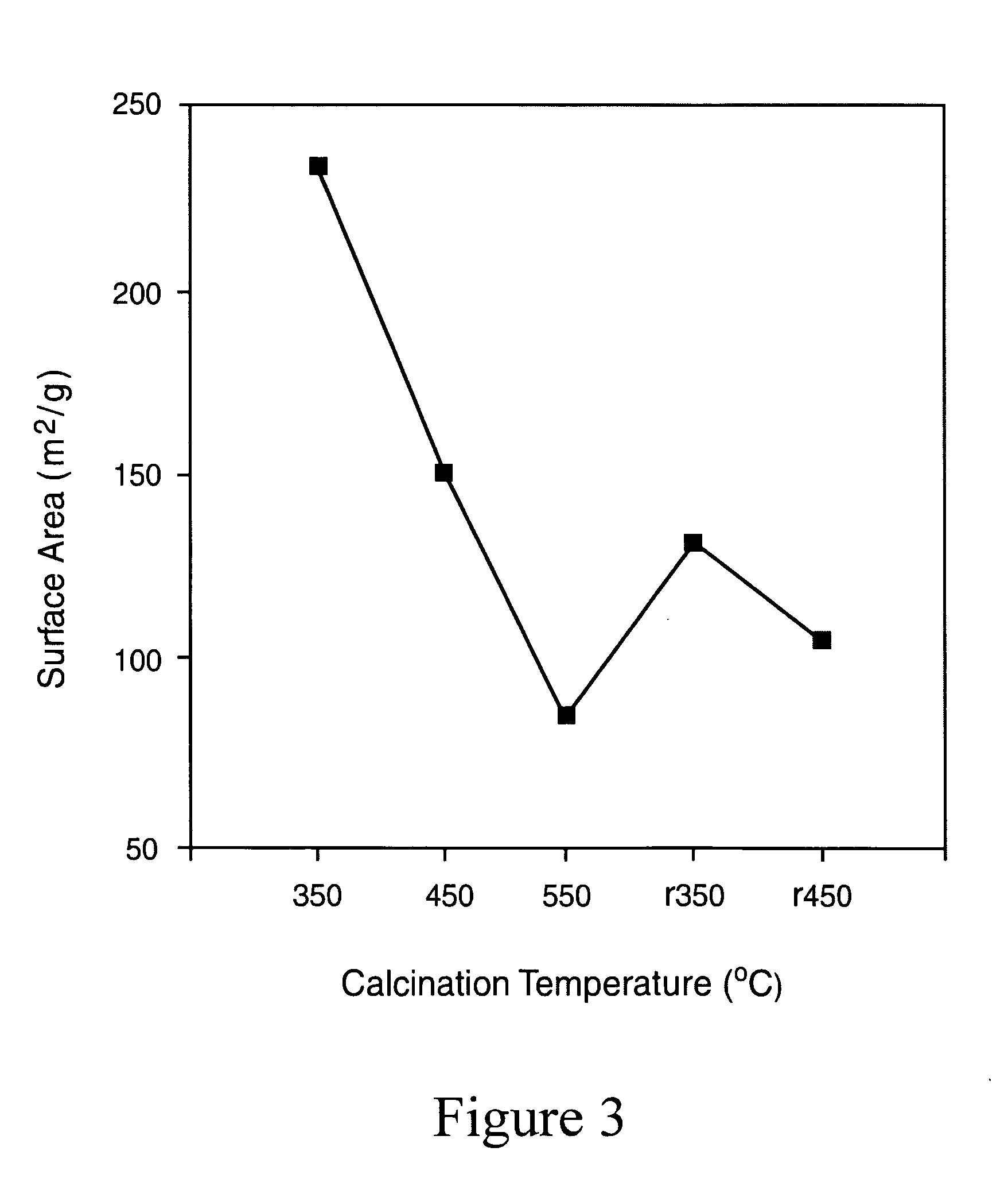
[0103]20 g of TiCl4 (digested to 50% in HCl) was added to 1000 mL of water. 80 g of guanidine nitrate was added in to this solution under magnetic stirring. The resulting mixture was then heated to 100° C. Development of white color is observed within an hour. The reaction was continued at that temperature for 24 h. After the reaction was cooled to room temperature, centrifuged, and washed with water three times to remove the chlorides and any other water-soluble reactants. The product was then dried at 60° C. overnight, powdered and calcined at temperatures 350, and 450° C. for 2 h (named as Ti R350, TiR450) to obtain the final yellow colored products.

example 2

Alternative Synthesis of a Titanium Dioxide Photocatalyst Using Guanidine Nitrate

[0104]20 g of TiCl4 (digested to 50% in HCl) was added to 1000 mL of water. 80 g of guanidine nitrate was then added to the solution and magnetically stirred for 30 minutes. Ammonium hydroxide solution was then added to bring the pH of the solution to 9. The reaction was continued at room temperature for 24 h. The ensuing precipitate was then centrifuged, washed with water three times to remove the chlorides and any other water-soluble reactants. The product was then dried at 60° C. overnight, powdered, and calcined at temperatures 350, 450 and 550° C. for 2 h (Ti350, Ti450, Ti550) to obtain the final bright yellow colored products.

example 3

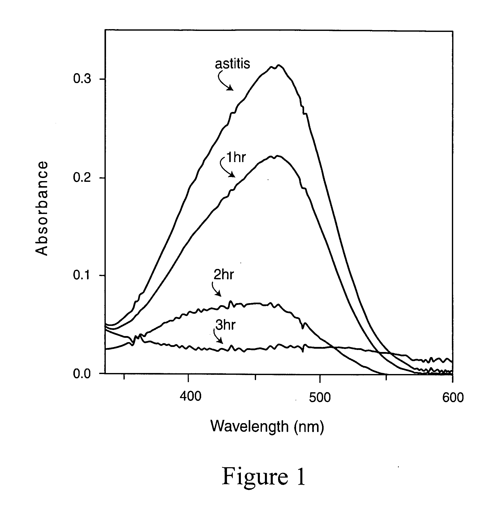
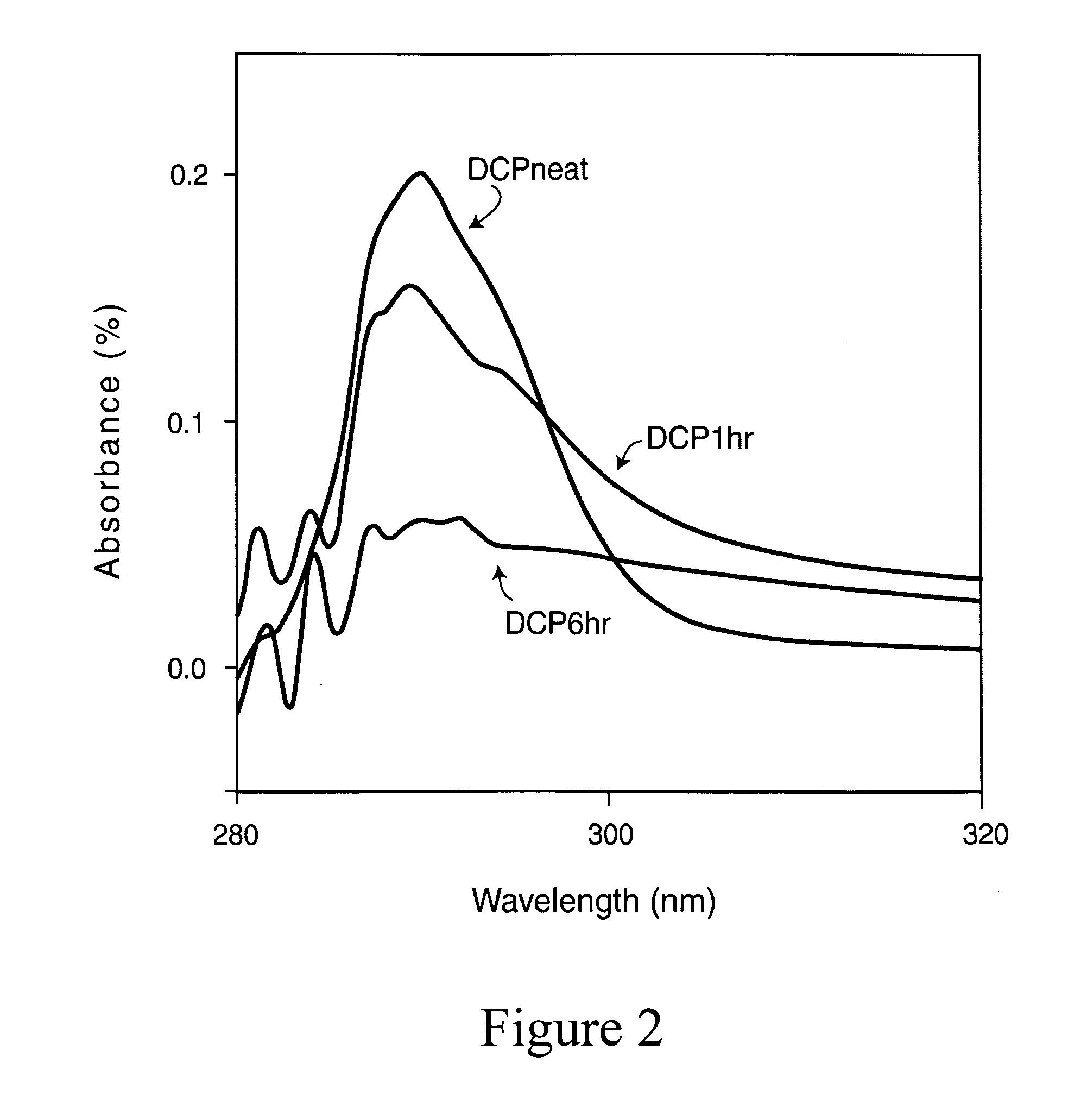
Analysis of the Effectiveness of the Catalyst by Degradation of Methyl Orange (MO) Dye

[0105]The degradation of MO was explored at varying concentrations of the catalyst (0.01-0.05 g), MO, and oxygen atmosphere. 30 mL (100 ppm concentration) of MO solution was taken in a reactor of 50 mL capacity and charged with a magnetic stir bar. 0.03 g catalyst was then added to it. The mixture was then sonicated for 2 min and inserted into a water-circulating jacket. The reaction mixture was stirred magnetically in the dark for 15 minutes to ensure the establishment of adsorption desorption equilibrium among the reactants and catalyst. After 15 minutes, two florescent light bulb of 100 watt were put on. The distance of the bulbs from the reactor was maintained at 30 cm. Aliquots were collected each ½ h.

[0106]The same reaction was repeated under the sunlight.

[0107]For reusing the catalyst, the reaction mixture was centrifuged and the collected catalyst was washed with water three times by redisp...


PUM

PropertyMeasurementUnit
Sizeaaaaaaaaaa
Specific surface areaaaaaaaaaaa
Temperatureaaaaaaaaaa

Abstract

Methods for preparing and using a photocatalyst are described. The catalyst is prepared by oxidation of a metal salt which has been doped in situ to form a photocatalyst active in visible light. The photocatalyst is used for degrading toxic and irritating compounds and infectious agents.

Description

FIELD OF THE INVENTION[0001]The present invention relates to catalyst compositions and methods for preparing and using them for photocatalyzing organic compounds.BACKGROUND OF INVENTION[0002]In recent years, it has been recognized that both chemical synthesis and chemical degradation are preferably performed using technologies that are more sustainable, less hazardous, less polluting and with less byproduct waste. Among other technologies, photocatalysts have been recognized as desirable.[0003]Over the years many have attempted and considerable effort has been applied to develop photocatalysts which can act as self-cleaning coatings, anti-microbial coatings and surfaces degrading organic contaminants, particularly those not readily biodegradable. Titanium dioxide (TiO2) has been of particular interest due to its low cost, almost no toxicity, chemical stability (both to light and the environment) and high photoactivity.[0004]TiO2 is a semiconductor with a number of properties pertine...

Claims


Application Information

Patent Timeline
IPC IPC(8): B01J19/08B01J27/02B01J31/06B01J27/24B01J21/06B01J31/38
CPCA61L9/00B01J38/50B01J21/063B01J23/50B01J27/24B01J27/28B01J35/002B01J35/004B01J35/023B01J35/1014B01J35/1019B01J37/031B01J38/02B01J38/48A61L9/205
Inventor VARMA, RAJENDER S.BARUWATI, BABITAVIRKUTYTE, JURATE
Owner ENVIRONMENTAL PROTECTION AGENCY US
Why Eureka
Try Eureka