Electrochromic devices

Active Publication Date: 2011-11-03
VIEW INC
View PDF1 Cites 319 Cited by
  • Summary
  • Abstract
  • Description
  • Claims
  • Application Information

AI Technical Summary

Benefits of technology

[0005]A typical electrochromic device includes an electrochromic (“EC”) electrode layer and a counter electrode (“CE”) layer, separated by an ionically conductive (“IC”) layer that is highly conductive to ions and highly resistive to electrons. In other words, the ionically conductive layer permits transport of ions but blocks electronic current. As conventionally understood, the ionically conductive layer therefore prevents shorting between the electrochromic layer and the counter electrode layer. The io

Problems solved by technology

While electrochromism was discovered in the 1960's, electrochromic devices still unfortuna

Method used


Image

  • Electrochromic devices
  • Electrochromic devices
  • Electrochromic devices

Examples


examples

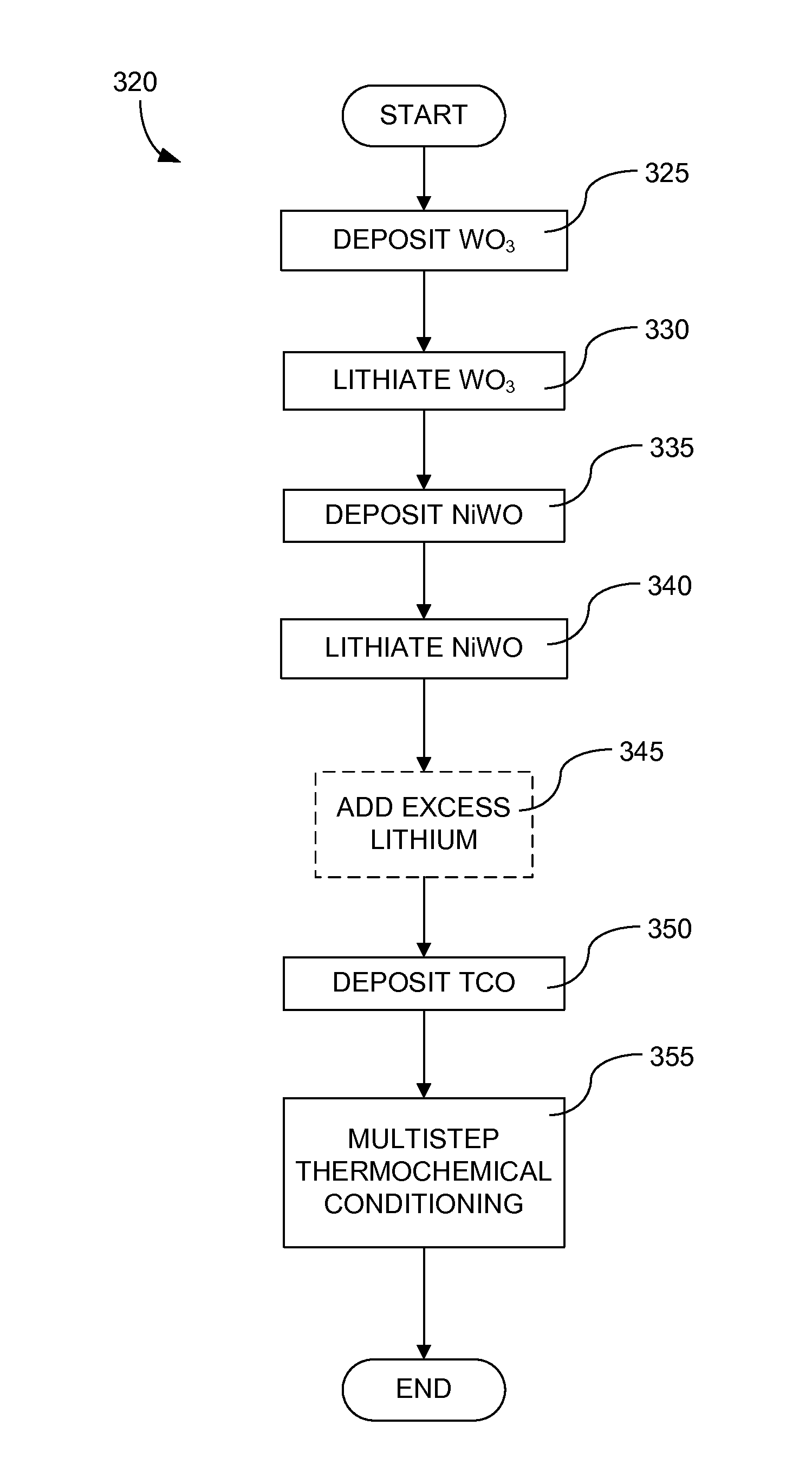
[0124]FIG. 6, is a graph of a process flow used as a protocol for fabricating electrochromic devices of the invention. They axis units are optical density and the x axis units are time / process flow. In this example, an electrochromic device is fabricated analogous to that described in relation to FIG. 4A, where the substrate is glass with fluorinated tin oxide as the first TCO, the EC layer is WO3 with excess oxygen in the matrix (for example, sputtered using the tungsten target, where the sputter gas is about 60% O2 and about 40% Ar), the CE layer is formed atop the EC layer and is made of NiWO and the second TCO is indium tin oxide (ITO). Lithium is used as the ion source for the electrochromic transition.

[0125]Optical density is used to determine endpoints during fabrication of the electrochromic device. Starting at the origin of the graph, optical density is measured as the EC layer, WO3, is deposited on the substrate (glass+TCO). The optical density of the glass substrate has a...


PUM

PropertyMeasurementUnit
Temperatureaaaaaaaaaa

Abstract

Conventional electrochromic devices frequently suffer from poor reliability and poor performance. Improvements are made using entirely solid and inorganic materials. Electrochromic devices are fabricated by forming an ion conducting electronically-insulating interfacial region that serves as an IC layer. In some methods, the interfacial region is formed after formation of an electrochromic and a counter electrode layer. The interfacial region contains an ion conducting electronically-insulating material along with components of the electrochromic and/or the counter electrode layer. Materials and microstructure of the electrochromic devices provide improvements in performance and reliability over conventional devices.

Description

CROSS-REFERENCE TO RELATED APPLICATIONS[0001]This application is a continuation in part of U.S. application Ser. No. 12 / 772,055 (Docket No. SLDMP004), filed Apr. 30, 2010, entitled “Electrochromic Devices”, the content of which is incorporated herein by reference in its entirety.BACKGROUND[0002]Electrochromism is a phenomenon in which a material exhibits a reversible electrochemically-mediated change in an optical property when placed in a different electronic state, typically by being subjected to a voltage change. The optical property is typically one or more of color, transmittance, absorbance, and reflectance. One well known electrochromic material, for example, is tungsten oxide (WO3). Tungsten oxide is a cathodic electrochromic material in which a coloration transition, transparent to blue, occurs by electrochemical reduction.[0003]Electrochromic materials may be incorporated into, for example, windows and mirrors. The color, transmittance, absorbance, and / or reflectance of su...

Claims


Application Information

Patent Timeline
IPC IPC(8): C23C14/08C23C14/34
CPCG02F1/1525C23C14/083
Inventor WANG, ZHONGCHUNPRADHAN, ANSHUROZBICKI, ROBERT
Owner VIEW INC
Why Eureka
Try Eureka