Method for cleaning filter separation systems

a filter separation and filter technology, applied in the direction of membrane technology, water/sludge/sewage treatment, chemistry apparatus and processes, etc., can solve the problems of filter fouling, mass transport through the filter per unit time, flux reduction, etc., and achieve the effect of enhancing filtration

Inactive Publication Date: 2011-11-03
BAKER HUGHES INC
View PDF6 Cites 5 Cited by
  • Summary
  • Abstract
  • Description
  • Claims
  • Application Information

AI Technical Summary

Benefits of technology

[0010]In one aspect, the invention is a method for enhancing filtration through a filter separation system including introducing a fouling reduction agent into a cleaning fluid to produce a treated cleaning fluid and then passing the treated cleaning fluid through the filter separation system, wherein the fouling reduction agent is a solid. In some embodiments, the solid is selected from the group consisting of powdered cellulose, powdered clays, diatomaceous earth, silica, alumina, calcium carbonate, and perlite. In other embodiments, the membrane separation system is used for reverse osmosis, nano-filtration, and ultra-filtration. In still other embodiments, the filter separation system is a membrane type high shear system such as a VSEP® system.

Problems solved by technology

A common problem in virtually all separation systems having a filter is fouling of the filter.
This retentate layer may include components which bind to the filter and clog its pores, thereby fouling the filter, or may remain as a stagnant boundary layer, either of which hinders transport of the components trying to pass through the filter to the downstream side of the filter.
In essence, mass transport through the filter per unit time, i.e., flux, may be reduced and the inherent sieving or trapping capability of the filter may be adversely affected.

Method used


Image

  • Method for cleaning filter separation systems
  • Method for cleaning filter separation systems
  • Method for cleaning filter separation systems

Examples


example 1

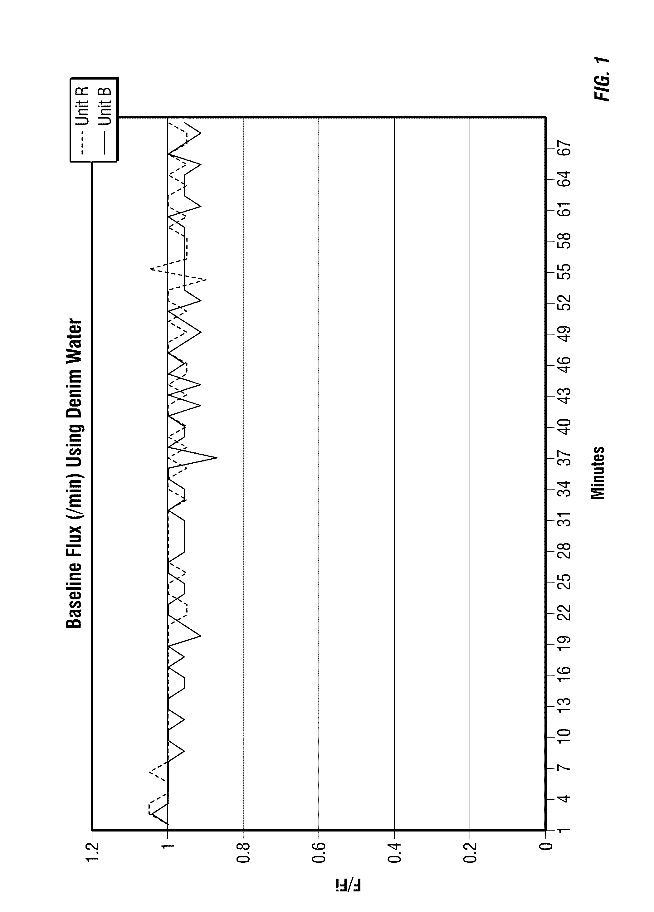
[0030]2 membrane separation system were tested using demineralized water at 500 PSI and at 122° F. The flux rate through both units was determined and the result are shown in FIG. 1. Note that both unites were operating essentially identically after the demineralized water test.

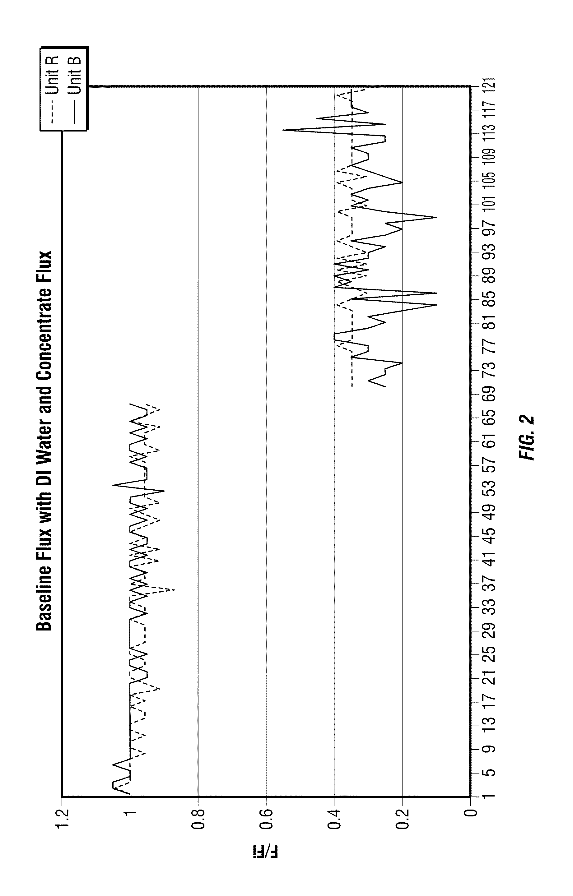
[0031]Then concentrated solids feed without the normal addition of surfactant and chelant was introduced into both units. The surfactant and chelant tend to reduce the amount of foulant on the membrane. In this test, fouling was maximized to increase the foulant deposited on the membrane. After 96 hours of concentration, the flux for both units was determined and displayed in FIG. 2. The graph below shows the change in flux from a clean membrane using demineralized water to a fouled membrane using concentrate solids feed. Note that the reduction in flux for both systems is essentially the same.

[0032]Both units were rinsed, filled with deionized water and the flux was retested. In FIG. 3, the data from the ret...

example 2

[0034]Heavily and identically fouled membranes were cleaned using different solids. All membranes were prepared by filtering a high solids feed with no surfactant or chelant for 72 hours. Various 1% suspensions were tested. The suspensions were added to the test apparatus and allowed to mix for 16 hours.

[0035]FIG. 5 shows a membrane treated with a 1% concentration of powdered calcium carbonate. Some foulant has been removed and this test is used as a baseline to indicate that the agent is effective.

[0036]FIG. 6 shows a membrane treated with a 1% suspension of bentonite. Note that more of the deposit has been removed.

[0037]FIG. 7 shows a membrane treated with a suspension of an admixture (0.5%) of bentonite and (0.5%) diatomaceous earth. Note that even more of the deposit has been removed.

[0038]FIG. 8 shows a membrane treated with a 1% suspension of powdered cellulose. Note that this composition resulted in the most deposit having been removed.


PUM


Abstract

High shear separations of suspensions and colloid suspensions may be preformed using a fouling reduction agent to optimize the separations. The fouling reduction agents are solids. Exemplary of such solids are powdered cellulose, clays, diatomaceous earth and the like. Process streams which may treated include refinery process waste water, chemical process waste water, food processing waste water, power generation waste water, chemical product streams, and chemical intermediate streams.

Description

CROSS-REFERENCE TO RELATED APPLICATIONS[0001]This application claims priority from U.S. Provisional Application Ser. No. 61 / 328,737, filed Apr. 28, 2010, the disclosure of which is incorporated herein by reference in its entirety.BACKGROUND[0002]1. Field of the Disclosure[0003]The invention relates to the separation of solids from a liquid using a filter separation method and methods of reducing fouling thereof. The invention particularly relates to enhancements to a method for reducing fouling of a high shear filter separation system.[0004]2. Background of the Disclosure[0005]Where fluids are contaminated with undesirable solids or where desirable solids are suspended in fluids, separation devices are typically utilized to separate the solids from the fluid. There are a wide variety of different separation methods. Exemplary methods include but are not limited to microfiltration, ultrafiltration, nanofiltration, reverse osmosis (hyperfiltration), dialysis, electrodialysis, prevapor...

Claims


Application Information

Patent Timeline
Patent Type & Authority Applications(United States)
IPC IPC(8): B01D65/02
CPCB01D2321/2091B01D65/02B01D65/04
Inventor KAJDASZ, RALPH J.DUNN, SIDNEY
Owner BAKER HUGHES INC
Why Eureka
Try Eureka