
Magnetic Scanning System with Improved Efficiency

a scanning system and efficiency technology, applied in the direction of beam deviation/focusing, instruments, beam current loss, etc., can solve the problems of large beam envelope, high power requirements of magnetic scanners, and loss of beam current, so as to facilitate ion implantation and reduce the amount of power required

Active Publication Date: 2011-11-03
AXCELIS TECHNOLOGIES
View PDF0 Cites 2 Cited by
  • Summary
  • Abstract
  • Description
  • Claims
  • Application Information

AI Technical Summary

Benefits of technology

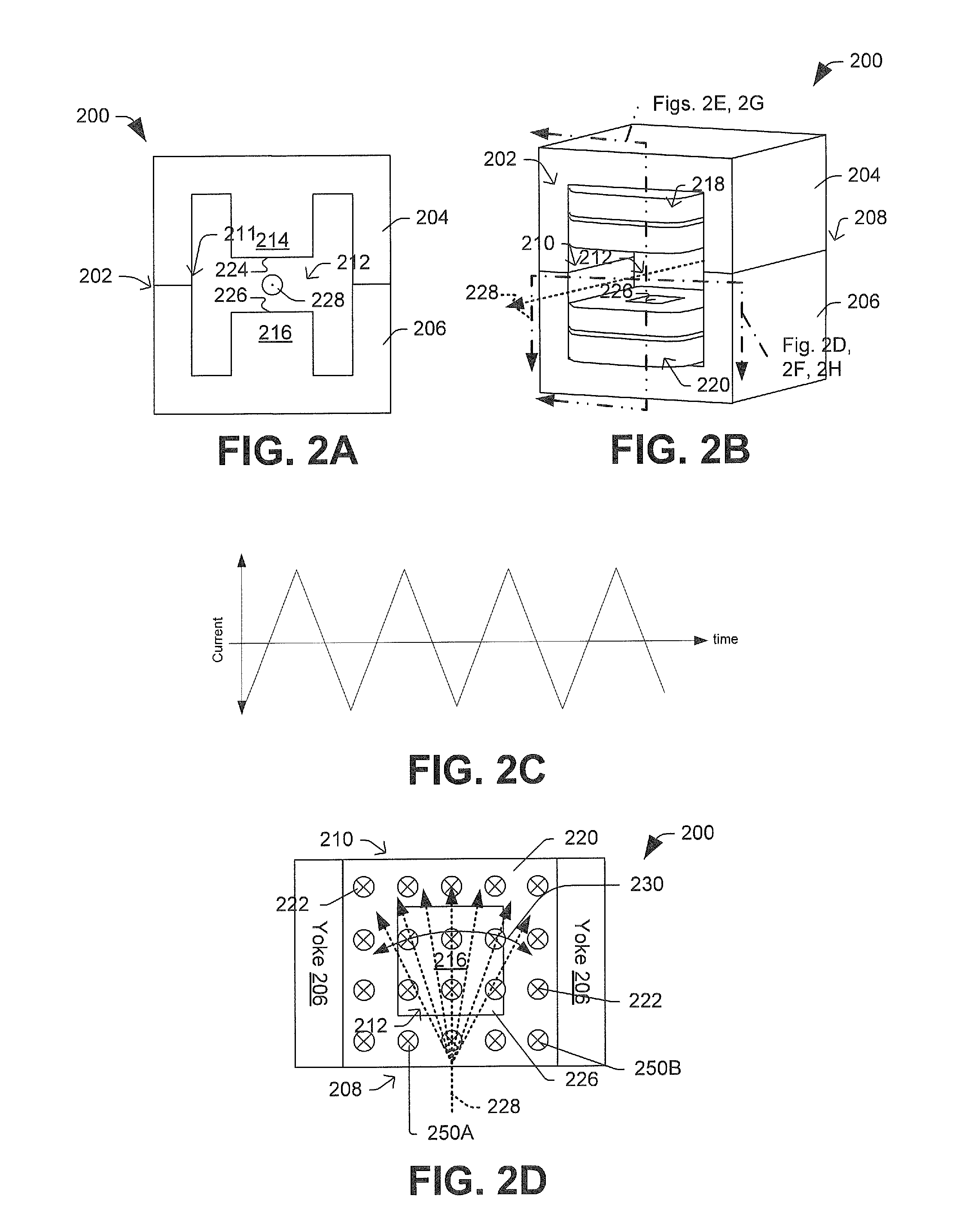
[0010]During operation, the first and second magnetic elements cooperatively generate an oscillatory time-varying magnetic field in the beam path region to scan an ion beam back and forth in time. The one or more magnetic flux compression elements compress the magnetic flux associated with the magnetic field in the beam region, thereby reducing the amount of power required to magnetically scan the beam back and forth, relative to previous implementations.

Problems solved by technology

One drawback to electric scanners is that, by their very nature they generate an electric field, and thus they attract electrons to positive electrodes or repel them far from negative electrodes.
This can cause beam blow up, sometimes resulting in an unmanageably large beam envelope.
This large beam envelope can ultimately result in beam current loss.
Although a magnetic scanner does not suffer from the space-charge blow-up like an electric scanner, magnetic scanners tend to require high powers to operate.
Generally speaking, the higher the operating power, the more expensive the power source and the greater care exercised with respect thereto.

Method used


Image

  • Magnetic Scanning System with Improved Efficiency
  • Magnetic Scanning System with Improved Efficiency
  • Magnetic Scanning System with Improved Efficiency

Examples


Embodiment Construction

[0025]The present invention will now be described with reference to the drawings wherein like reference numerals are used to refer to like elements throughout, and wherein the illustrated structures are not necessarily drawn to scale.

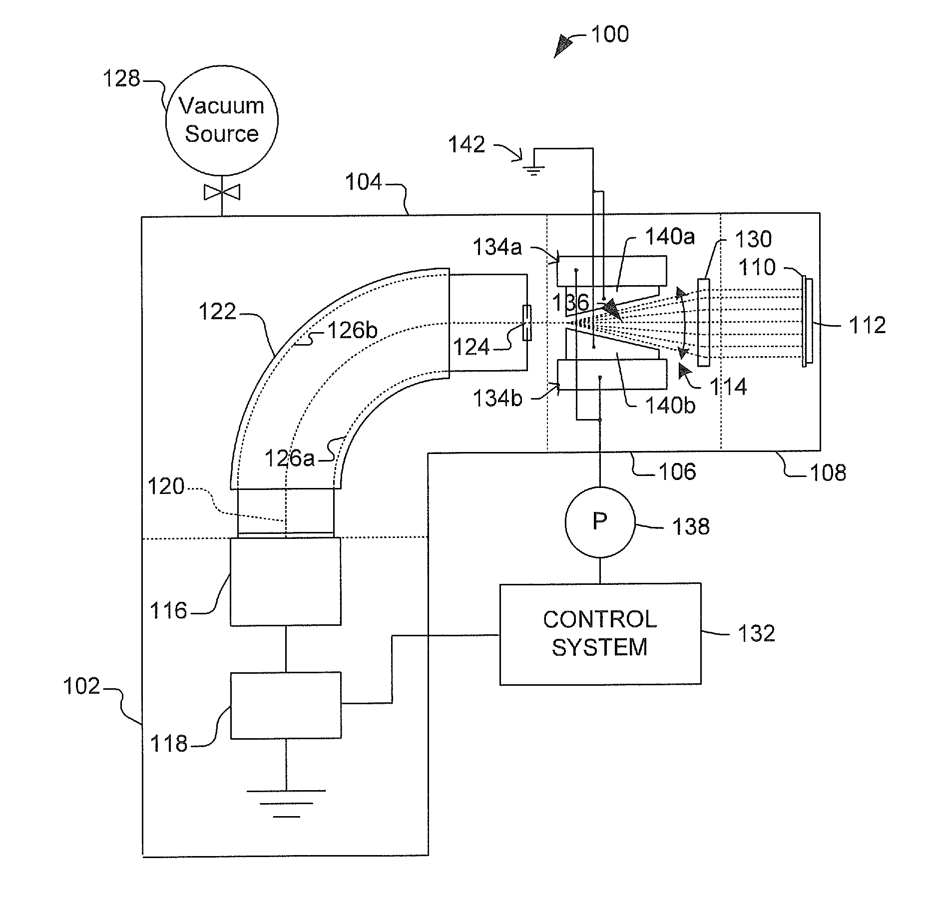
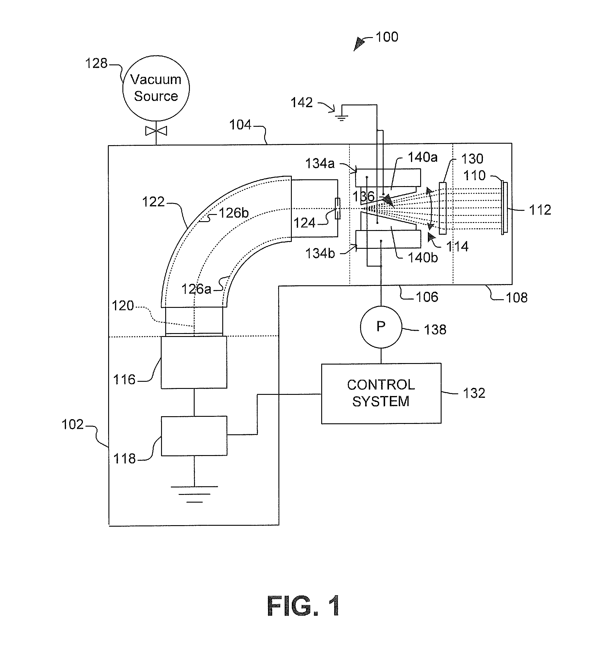
[0026]FIG. 1 illustrates an ion implantation system 100 having a source terminal 102, beamline assembly 104, magnetic scan system 106, and end station 108, which are collectively arranged so as to inject ions (dopants) into the lattice of a workpiece 110 according to a desired dosing profile. In particular, FIG. 1 illustrates a hybrid-scan ion implantation system 100, wherein a moveable stage 112 is operable to translate the workpiece 110 along a first axis (e.g., into the plane of the page in FIG. 1) while the magnetic scan system 106 provides a scanned ion beam 114 along a second axis perpendicular to the first axis. By scanning the ion beam with respect to the workpiece in this manner, the entire surface of the workpiece can be implanted until a desi...


PUM


Abstract

Some aspects of the present invention facilitate ion implantation by using a magnetic beam scanner that includes first and second magnetic elements having a beam path region therebetween. One or more magnetic flux compression elements are disposed proximate to the beam path region and between the first and second magnetic elements. During operation, the first and magnetic elements cooperatively generate an oscillatory time-varying magnetic field in the beam path region to scan an ion beam back and forth in time. The one or more magnetic flux compression elements compress the magnetic flux provided by the first and second magnetic elements, thereby reducing the amount of power required to magnetically scan the beam back and forth (relative to previous implementations). Other scanners, systems, and methods are also disclosed.

Description

BACKGROUND[0001]In ion implantation systems, an ion beam is directed towards a work piece (e.g., a semiconductor wafer, or a display panel), and implants ions into a lattice thereof. Once embedded into the lattice of the workpiece, the implanted ions change the physical and / or chemical properties of the workpiece. Because of this, ion implantation is used in semiconductor device fabrication, in metal finishing, and for various applications in materials science research.[0002]The ion implantation application space is historically divided into low dose (medium current), high energy and high dose (high current) applications.[0003]In high current applications the cross-sectional area of a high current ion beam can vary depending on the extent of self-neutralization occurring in the beam, among other factors. In self-neutralization, which occurs in absence of an electric field, the ion beam can attract free electrons near the beam path. This tends to limit beam “blow-up”, thereby helping...

Claims


Application Information

Patent Timeline
Patent Type & Authority Applications(United States)
IPC IPC(8): H01J37/147H01J37/317
CPCH01J37/1475H01J2237/1526H01J2237/1523H01J37/3171H01J37/147H01J37/317
Inventor VANDERBERG, BO
Owner AXCELIS TECHNOLOGIES
Learn More