Systems and methods for beam angle adjustment in ion implanters

a beam angle adjustment and beam technology, applied in the field of ion implantation systems, can solve the problems of increasing the complexity of the ion implantation system, uncontrollable and/or undesired implant properties, undesired increase in the length of the path along which the ion beam travels, etc., and achieve the effect of facilitating ion implantation

Active Publication Date: 2007-06-05
AXCELIS TECHNOLOGIES
View PDF4 Cites 23 Cited by
  • Summary
  • Abstract
  • Description
  • Claims
  • Application Information

AI Technical Summary

Benefits of technology

[0009]Aspects of the present invention facilitate ion implantation by performing angle adjustments without additional components being added to ion implantation systems. The aspects employ a mass analyzer to perform selected angle adjustments during ion implantation instead of employing separate and / or additional components.

Problems solved by technology

A non-uniform angular distribution or angular content of the ion beam can lead to uncontrolled and / or undesired implant properties.
However, conventional approaches can increase complexity of the ion implantation system and undesirably increase the length of path along which the ion beam travels.

Method used


Image

  • Systems and methods for beam angle adjustment in ion implanters
  • Systems and methods for beam angle adjustment in ion implanters
  • Systems and methods for beam angle adjustment in ion implanters

Examples


Embodiment Construction

[0019]The present invention will now be described with reference to the drawings wherein like reference numerals are used to refer to like elements throughout, and wherein the illustrated structures are not necessarily drawn to scale.

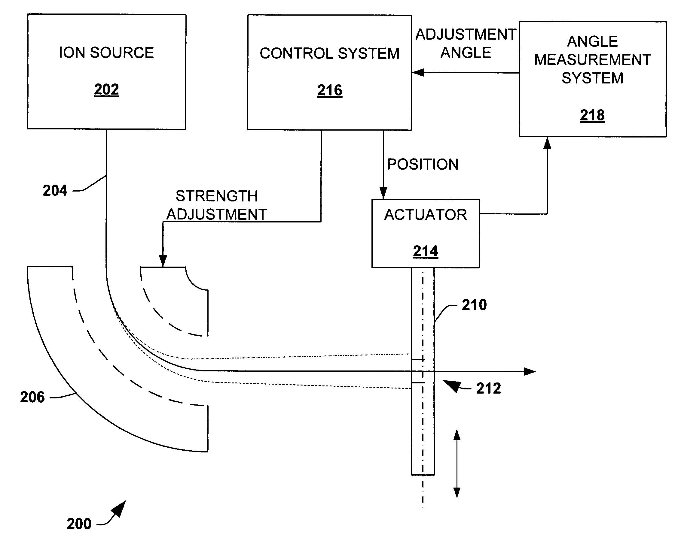
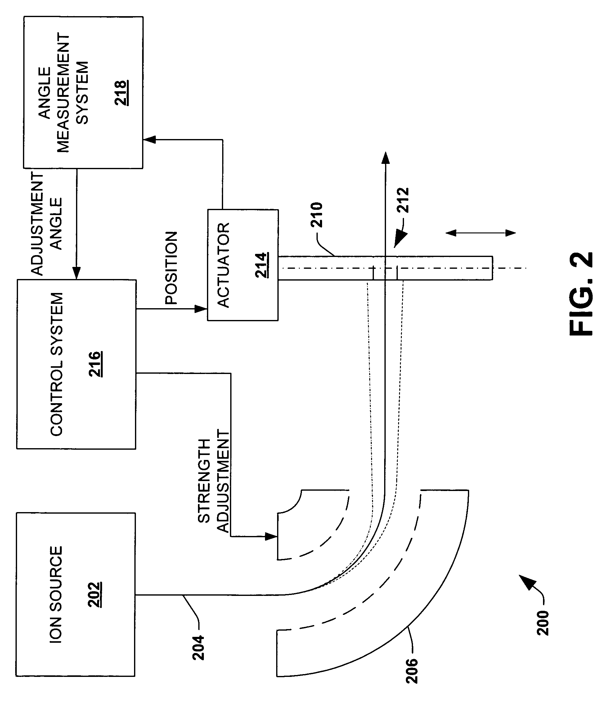
[0020]Aspects of the present invention facilitate ion implantation employing a mass analyzer to perform angle correction / adjustment in addition to mass analysis. As a result, angle corrections of the implant angle can be performed without additional components along the beam line.

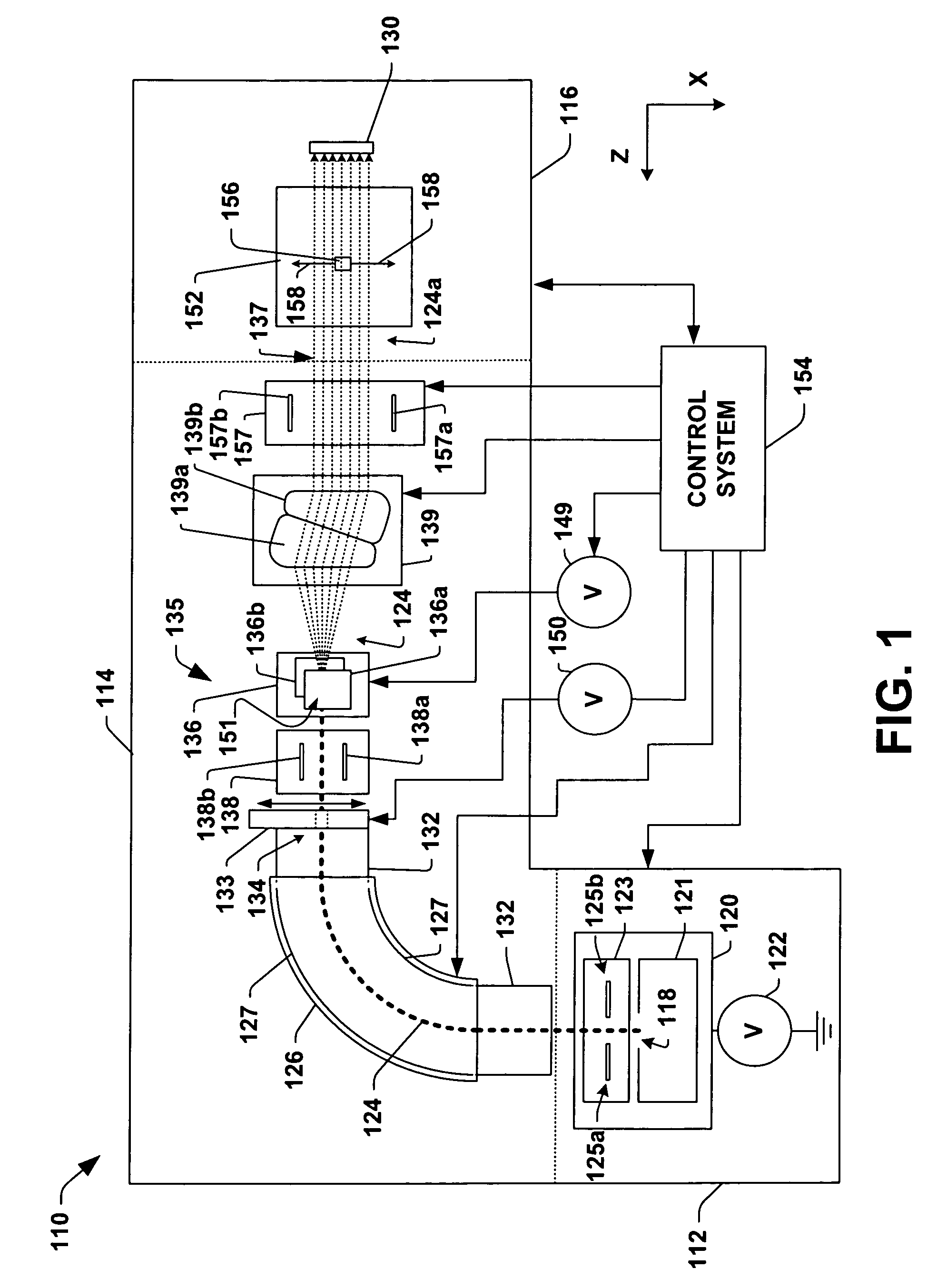
[0021]FIG. 1 illustrates an example ion implantation system 110 in accordance with an aspect of the present invention. The system 110 is presented for illustrative purposes and it is appreciated that aspects of the invention are not limited to the described ion implantation system and that other suitable ion implantation systems of varied configurations can also be employed.

[0022]The system 110 has a terminal 112, a beamline assembly 114, and an end station 116. The terminal 11...


PUM


Abstract

An ion implantation system employs a mass analyzer for both mass analysis and angle correction. An ion source generates an ion beam along a beam path. A mass analyzer is located downstream of the ion source that performs mass analysis and angle correction on the ion beam. A resolving aperture within an aperture assembly is located downstream of the mass analyzer component and along the beam path. The resolving aperture has a size and shape according to a selected mass resolution and a beam envelope of the ion beam. An angle measurement system is located downstream of the resolving aperture and obtains an angle of incidence value of the ion beam. A control system derives a magnetic field adjustment for the mass analyzer according to the angle of incidence value of the ion beam from the angle measurement system.

Description

FIELD OF THE INVENTION[0001]The present invention relates generally to ion implantation systems, and more specifically to systems and methods for performing beam angle adjustments of ion beams in ion implantation systems.BACKGROUND OF THE INVENTION[0002]In the manufacture of semiconductor devices, ion implantation is used to dope semiconductors with impurities or dopants. Ion beam implanters are used to treat silicon wafers with an ion beam, in order to produce n or p type extrinsic material doping or to form passivation layers during fabrication of an integrated circuit. When used for doping semiconductors, the ion beam implanter injects a selected extrinsic ion species to produce the desired semiconducting material. Implanting ions generated from source materials such as antimony, arsenic or phosphorus results in “n type” extrinsic material wafers, whereas if “p type” extrinsic material wafers are desired, ions generated with source materials such as boron, or indium may be implan...

Claims


Application Information

Patent Timeline
Patent Type & Authority Patents(United States)
IPC IPC(8): H01J37/08
CPCH01J37/3171H01J37/1471H01J37/1472H01J2237/24528
Inventor VANDERBERG, BO H.EISNER, EDWARD C.
Owner AXCELIS TECHNOLOGIES
Why Eureka
Try Eureka