Silicon condenser microphone having an additional back chamber and a fabrication method therefor

US20110266641A1Inactive Publication Date: 2011-11-03BSE CO LTD

Image

  • Silicon condenser microphone having an additional back chamber and a fabrication method therefor
  • Silicon condenser microphone having an additional back chamber and a fabrication method therefor
  • Silicon condenser microphone having an additional back chamber and a fabrication method therefor

Examples


Embodiment Construction

[0024]The present invention will now be described more fully with reference to the accompanying drawings, in which exemplary embodiments of the invention are shown. The invention may, however, be embodied in many different forms and should not be construed as being limited to the embodiments set forth herein.

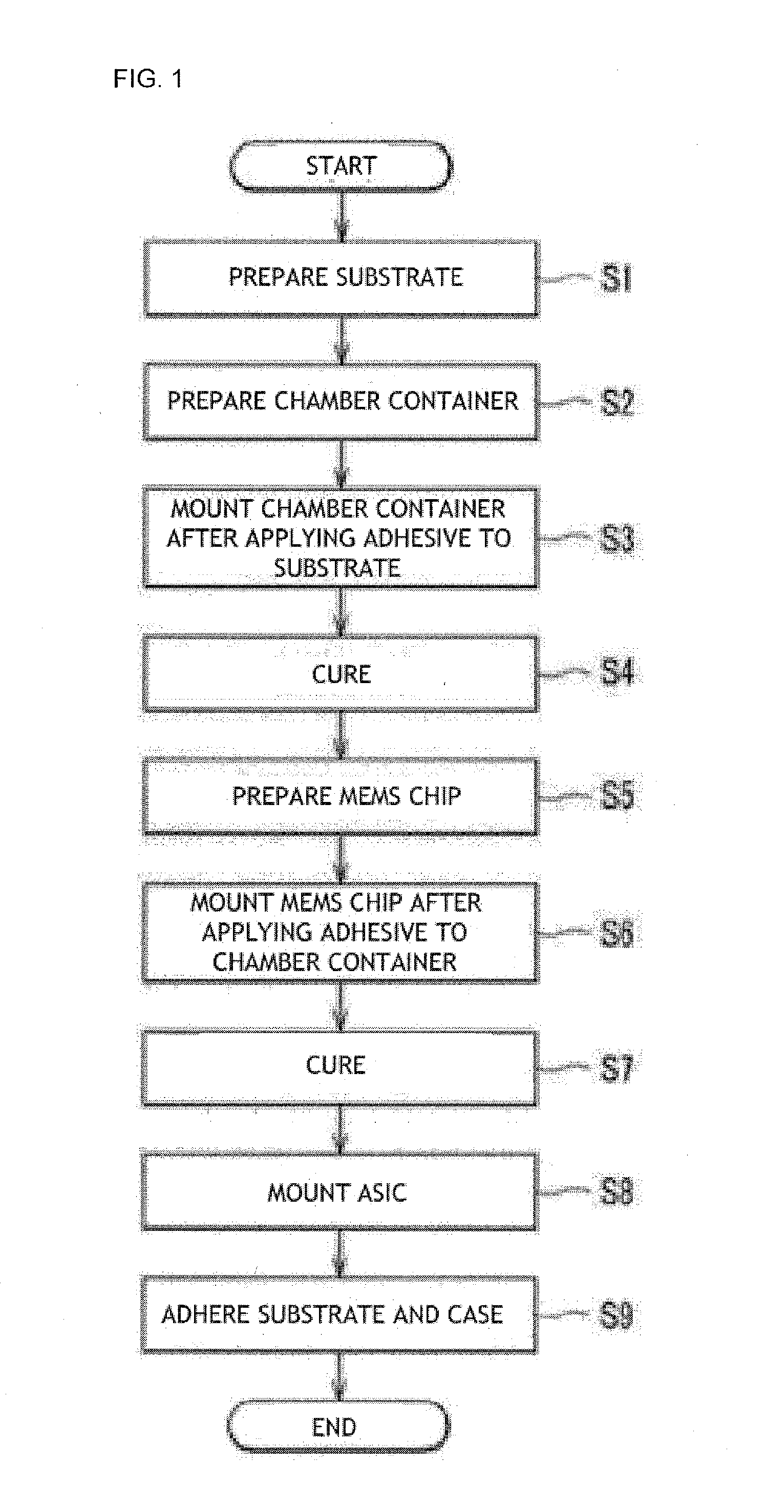
[0025]FIG. 1 is a flowchart showing a method of fabricating a silicon condenser microphone according to an embodiment of the present invention.

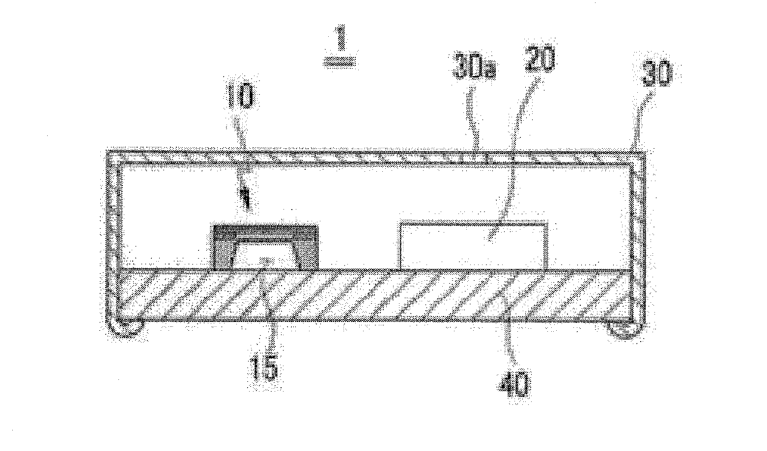
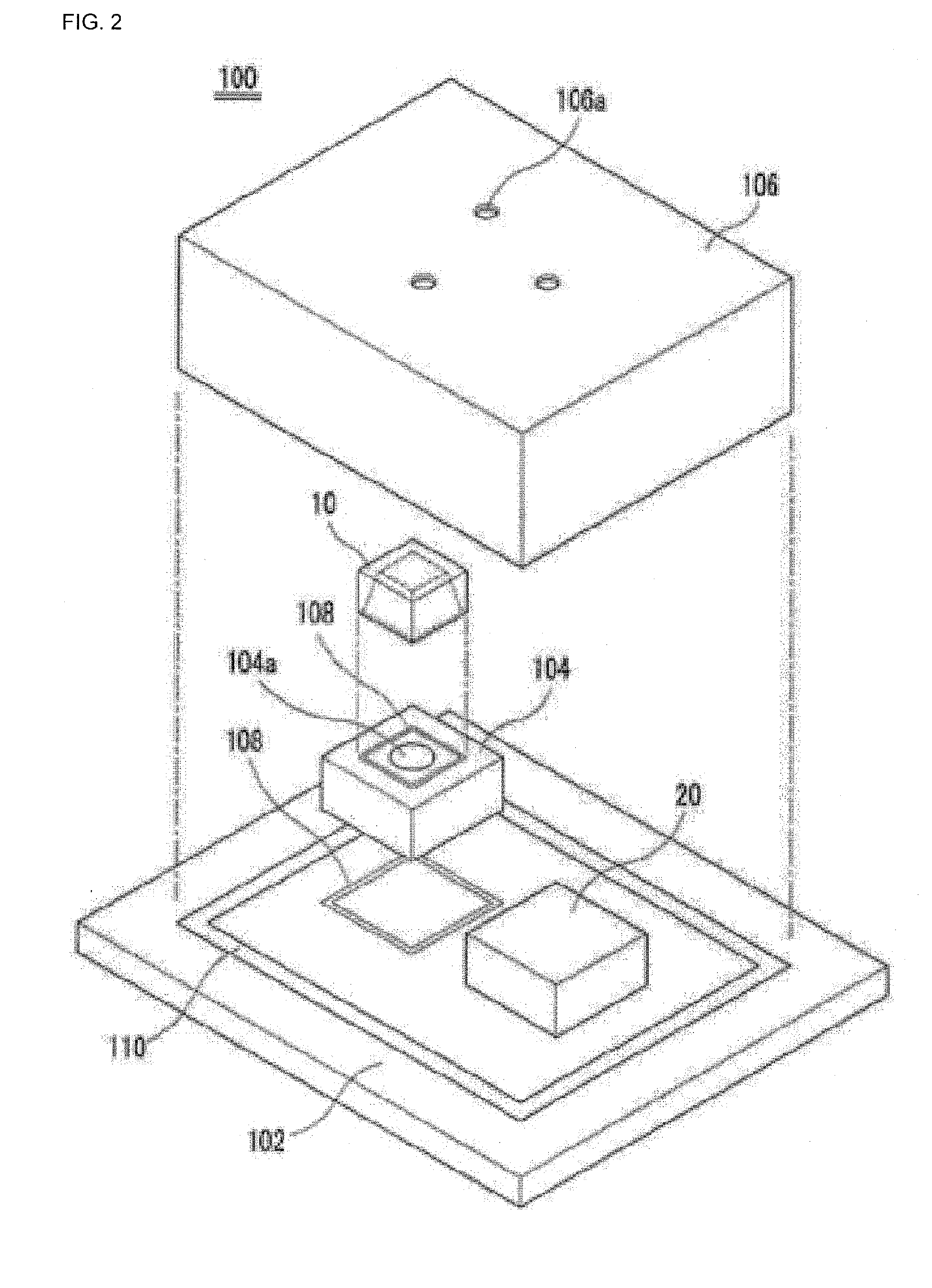
[0026]As shown in FIG. 1, the method of forming a silicon condenser microphone having an additional back chamber includes preparing a substrate (operation S1), preparing a chamber container (operation S2), applying an adhesive on the substrate and mounting the chamber container thereon by using a mounter (operation S3), curing the adhesive holding the chamber container at a predetermined temperature (operation S4), preparing a micro electro mechanical system (MEMS) chip (operation S5), applying an adhesive on the chamber container and mou...


PUM


Abstract

A fabrication method of a silicon condenser microphone having an additional back chamber. The method includes applying an adhesive on a substrate and mounting a chamber container thereon by using a mounter; curing the adhesive holding the chamber container; applying an adhesive on the chamber container and mounting a micro electro mechanical system (MEMS) chip thereon by using a mounter; curing the adhesive holding the MEMS chip; and attaching the substrate on which devices are mounted to a case, wherein a back chamber formed by the chamber container is added to a back chamber of the MEMS chip. Therefore, a silicon condenser microphone fabricated by using the method may have improved sensitivity by increasing the small back chamber space of the a micro electro mechanical system (MEMS) chip itself and reduced noise including total harmonic distortion (THD).

Description

TECHNICAL FIELD[0001]The present invention relates to a silicon condenser microphone and a method of fabricating the same, and more particularly, to a silicon condenser microphone having an additional back chamber and a method of fabricating the same.BACKGROUND ART[0002]Generally, a condenser microphone widely used in mobile communication terminals or mobile audio devices includes a voltage bias component, a pair of diaphragm / back plate for forming a capacitance C that changes in correspondence with sound pressures, and a field effect transistor (JFET) for buffering output signals. Such is a traditional type condenser microphone is completely formed as a single assembly by inserting a diaphragm, a spacer ring, an insulation ring, a back plate, and an electric current application ring into a single case in the stated order, inserting a PCB, on which circuit devices are mounted, into the case, and bending an end of the case toward the PCB.[0003]Recently, a semiconductor fabrication te...

Claims


Application Information

Patent Timeline
03 Nov 2011
Publication
US20110266641A1
IPC
H01L29/84; H01L21/52
CPC
H04R19/04; H01L2924/16152; H04R31/00; H04R2410/03; H04R2499/11
Inventors
SONG, CHUNG-DAM