Power generating apparatus, power generating system, and wireless electric power transmission apparatus

a power generator and power generating system technology, applied in the direction of exchanging data chargers, pv power plants, inductances, etc., can solve the problems of not being able to ignore, the cost of manufacturing those cells and modules is too high, and the installation cost of solar power generation systems is too high, so as to achieve the effect of reducing the cost of installing the power generator, reducing the cost of replacing a deteriorated part of the power generating section, and hardly

Active Publication Date: 2011-11-03
PANASONIC CORP
View PDF13 Cites 67 Cited by
  • Summary
  • Abstract
  • Description
  • Claims
  • Application Information

AI Technical Summary

Benefits of technology

[0028]In yet another preferred embodiment, the power-transmitting antenna includes multiple inductors that are connected together in series and multiple capacitors that are connected in series to the inductors. The transmitting-end control section chooses at least one of the inductors and at least one of the capacitors according to the output impedance value of the power generating section, and makes current flow through the at least one inductor chosen and the at least one capacitor chosen, thereby changing the input impedance of the power-transmitting antenna.
[0056]A power generator according to the present invention can transmit energy wirelessly through the air by a non-contact method. Thus, according to the present invention, the energy generated by a power generating section that is arranged outside of a building can be transmitted to an electronic device inside of that building. Thus, the cost of installing the power generator can be reduced and the job of replacing a deteriorated part of the power generating section can get done more easily.
[0057]In addition, according to the present invention, the output impedance of the power generator can be matched to the impedance of the transmission line according to the operating environment of the power generator. For that reason, the performance of the power generator hardly deteriorates even when the characteristics of respective elements of the power generator vary according to the irradiance of the sunlight received or the temperature. As a result, the power generator of the present invention can operate with high efficiency and good stability. Also, by arranging a number of power generators of the present invention in parallel with each other, a high efficiency and stabilized power generation system can be established. On top of that, the wireless power transmission system of the present invention can transmit the supplied DC energy with high efficiency and good stability, too.

Problems solved by technology

Such a solar power generation system, however, has not been widespread yet because the cost of manufacturing those cells and modules is too high, which is one of the major obstacles to its introduction.
On top of that, the cost of establishing such a system by installing those cells and modules is also too high to ignore.
Among other things, the higher the altitude of the place of installation, the riskier and the more expensive the installation work will be, which is a serious problem to overcome in order to further popularize the solar power generation system.
What is more, to introduce a solar power generation system into a non-new building, it is difficult to install to connect the solar power generating section outside of the building to electronic devices inside of the building, which is also one of the big problems with conventional solar power generation systems.
And a decrease in reliability at such a huge number of connection points is a decisive factor in the decline of the long-term reliability of the overall system.
Consequently, the cost of maintenance is non-negligible.
That is why as in the solar power generating device, a decrease in reliability at such a huge number of connection points is a decisive factor in the decline of the long-term reliability of the overall system.
The power supply system disclosed in Japanese Patent Application Laid-Open Publication No. 2006-136045, however, cannot overcome the solar power generation device's own problem that the output voltage of each cell is low.
It should be noted that even if the DC voltage is not converted into AC power within such a solar power generation system, a similar problem will also arise.
However, the greater the number of cells or modules to be connected together in series, the more easily the overall performance of the system will decline due to either so-called “partial shading” (i.e., some of the installation zone goes into the shade) or deterioration in the property of some of those cells or modules to be installed.
Such a measure is not preferred because an excessive quantity of heat will be generated or the cost will rise significantly in that case.
Meanwhile, even when the voltage needs to be increased using a normal DC / DC converter with a voltage boosting function, it is also difficult to achieve a voltage step-up ratio that is high enough to significantly reduce the number of cells to be connected together in series.
For that reason, if a fixed load is driven by a solar cell, mismatch may be caused between the output impedance of the cell and the impedance of the transmission line due to a variation in the intensity of the sunlight received or the temperature of the cell itself.
As a result, the power transmission efficiency will decrease.
In any case, it is difficult to maintain stabilized energy output under those environmental variations.

Method used


Image

  • Power generating apparatus, power generating system, and wireless electric power transmission apparatus
  • Power generating apparatus, power generating system, and wireless electric power transmission apparatus
  • Power generating apparatus, power generating system, and wireless electric power transmission apparatus

Examples


embodiment 1

[0099]Hereinafter, a First Preferred Embodiment of a power generator according to the present invention will be described with reference to FIGS. 5 through 21, in which any component also shown in FIGS. 1 through 4 and having substantially the same function as its counterpart is identified by the same reference numeral.

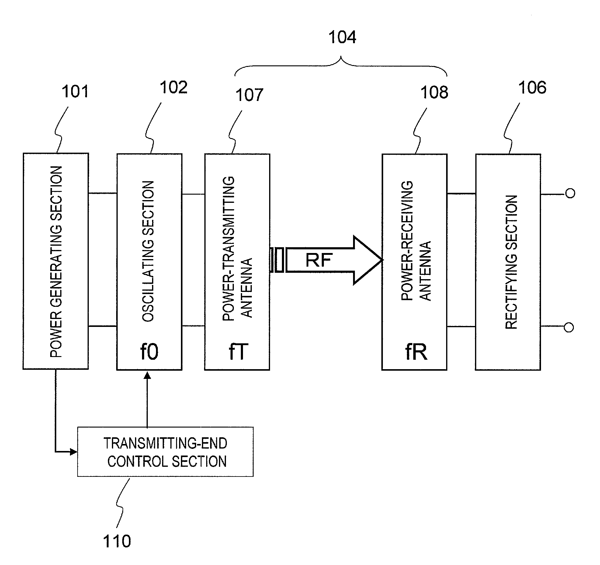
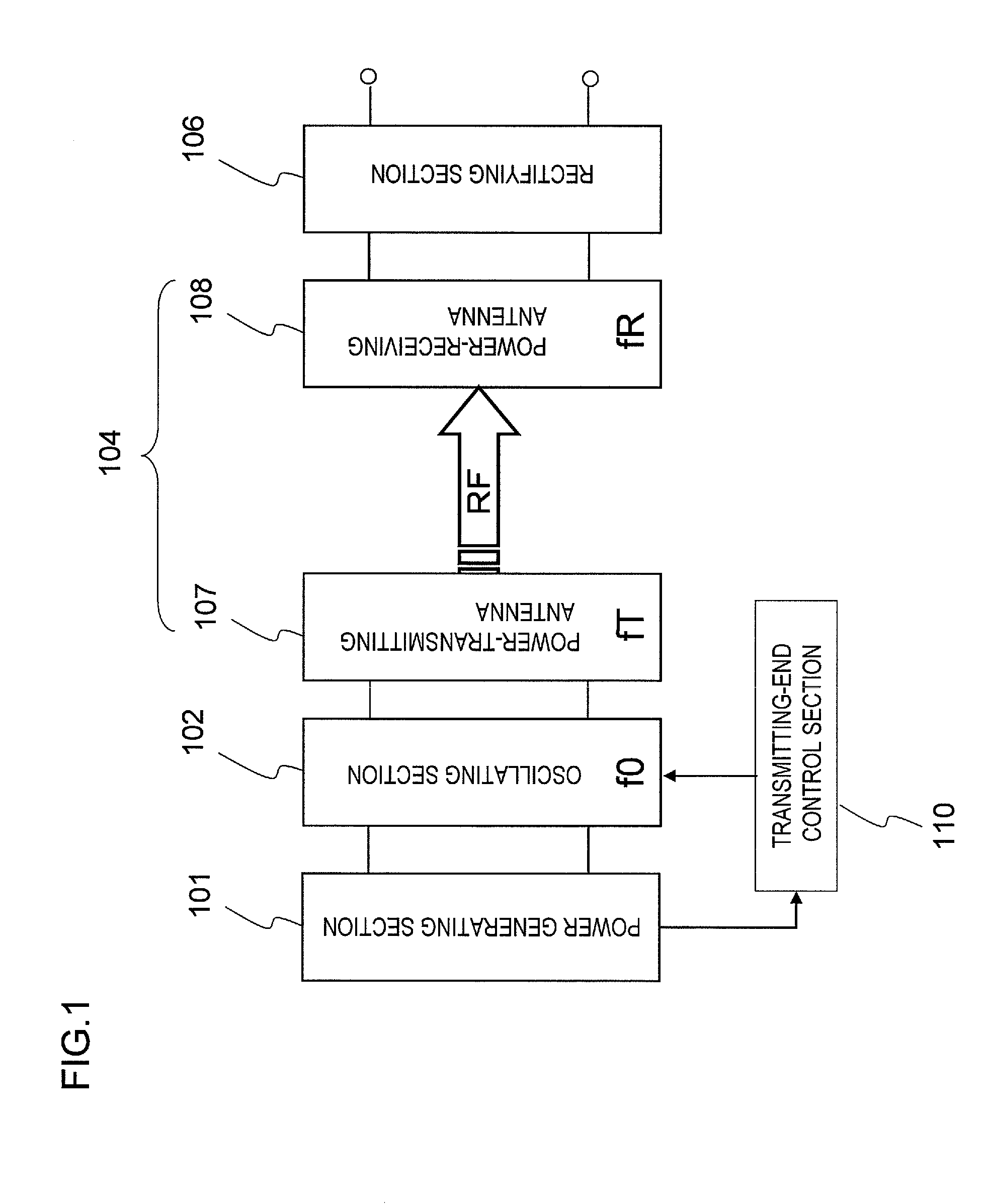
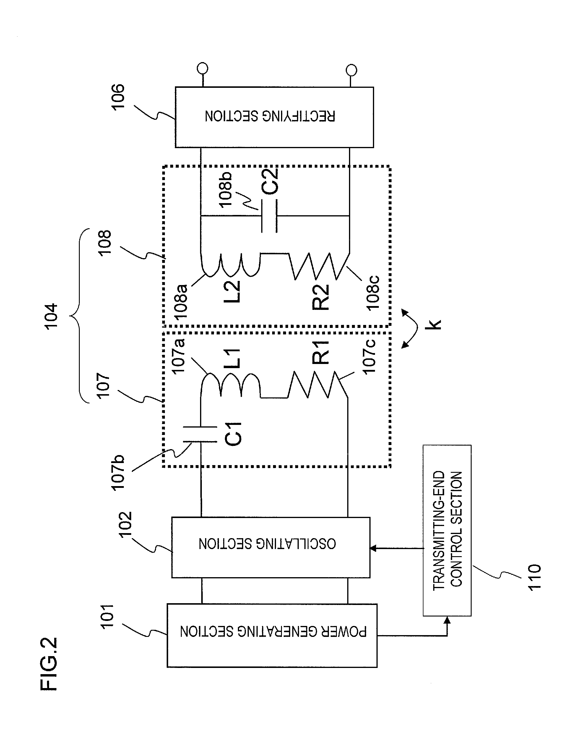
[0100]FIG. 5 is a schematic representation illustrating a configuration for a power generator as a first specific preferred embodiment of the present invention. As shown in FIG. 5, the power generator of this preferred embodiment includes a power generating section 101, an oscillating section 102, an impedance matching section for oscillating section 103, a wireless transmission section 104, a impedance matching section for rectifying section 105 and a rectifying section 106, which are connected together in series. The rectifying section 106 is connected to, and followed by, a load 113. The power generator further includes an output current and voltage measuring secti...

embodiment 2

[0185]Hereinafter, a preferred embodiment of a power generation system according to the present invention will be described with reference to FIG. 22, which is a block diagram illustrating a power generation system as a second specific preferred embodiment of the present invention. In FIG. 22, any component having substantially the same function as its counterpart of the power generator of the preferred embodiments described above is identified by that counterpart's reference numeral and the description thereof will be omitted herein to avoid redundancies.

[0186]The power generation system shown in FIG. 22 includes a number of power generators 131a, 131b, . . . and 131n that are arranged in parallel with each other. In this preferred embodiment, each of these power generators 131a, 131b, . . . and 131n has the arrangement of the first preferred embodiment described above. However, to achieve the effects of the present invention, the power generation system of the present invention ju...


PUM

PropertyMeasurementUnit
output voltageaaaaaaaaaa

Abstract

A power generator includes: a power generating section 101 that outputs DC energy; an oscillating section 102 that converts the DC energy into RF energy with a frequency f0; a power-transmitting antenna 107 that transmits the RF energy; a power-receiving antenna 108 that receives at least a part of the RF energy that has been transmitted by the power-transmitting antenna 107; and a transmitting-end control section 110 that matches the input impedance of the oscillating section 102 to the output impedance of the power generating section 101 by changing the input impedance of the oscillating section 102 in accordance with a variation in the output impedance of the power generating section 101. The power-transmitting antenna 107 is a series resonant circuit, and the power-receiving antenna 108 is a parallel resonant circuit. And the resonant frequencies fT and fR of the power-transmitting and power-receiving antennas 107 and 108 are both set to be equal to the frequency f0 of the RF energy.

Description

[0001]This application claims priority under 35 USC §119(e) to U.S. Provisional Application No. 61 / 330,426 filed on May 3, 2010, the entire contents of which are incorporated herein by reference.BACKGROUND OF THE INVENTION[0002]1. Field of the Invention[0003]The present invention relates to a power generator, power generation system and wireless power transmission system for transferring energy through the air.[0004]2. Description of the Related Art[0005]To avoid exhausting valuable natural resources and to cope with the global warming effect that has been growing year by year, people have been paying more and more attention to solar power generation that never releases harmful carbon dioxide. In fact, a power plant for generating a lot of electric power by installing a huge number of solar power generators (i.e., so-called “solar cells”, which will be sometimes simply referred to herein as “cells”) in a wide area has become a reality. In most cases, solar power generators for gener...

Claims


Application Information

Patent Timeline
Patent Type & Authority Applications(United States)
IPC IPC(8): H01F38/14
CPCH02J17/00H02J7/025H02S10/00H02J50/12H02J50/20H02J7/00034Y02E10/50H02J50/80
Inventor YAMAMOTO, HIROSHIKANNO, HIROSHI
Owner PANASONIC CORP
Why Eureka
Try Eureka