Electronic device

Inactive Publication Date: 2011-11-03
NGK INSULATORS LTD
View PDF2 Cites 12 Cited by
  • Summary
  • Abstract
  • Description
  • Claims
  • Application Information

AI Technical Summary

Benefits of technology

[0025]This configuration can provide “the electronic device comprising the layered piezoelectric

Problems solved by technology

However, after application of such an epoxy resin adhesive, a portion of the “resin and additive” contained in the adhesive may ooze from the site to which the adhesive was applied.
Therefore, when the electrode 100c is “an electrode for connecting the element 100 to an external circuit,” a problem may arise in that the area of a

Method used


Image

  • Electronic device
  • Electronic device
  • Electronic device

Examples


first embodiment

(Structure)

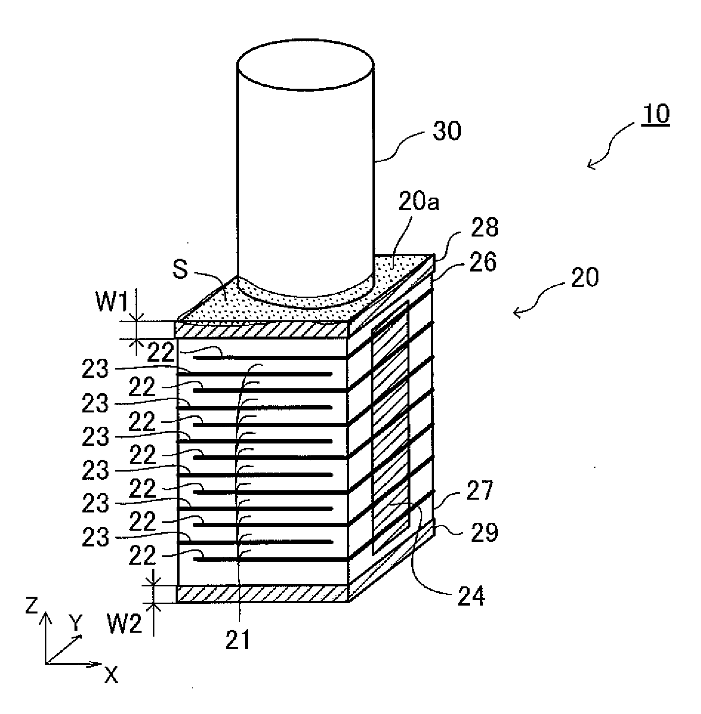
[0040]As shown in FIG. 1, an electronic device according to the first embodiment of the present invention (hereinafter may be referred to as “the first device”) 10 comprises a layered piezoelectric element (piezoelectric element) 20 and a driven member 30. The driven member 30 is, for example, a rod or a weight which slides or vibrates by expansion / contraction of the piezoelectric element 20.

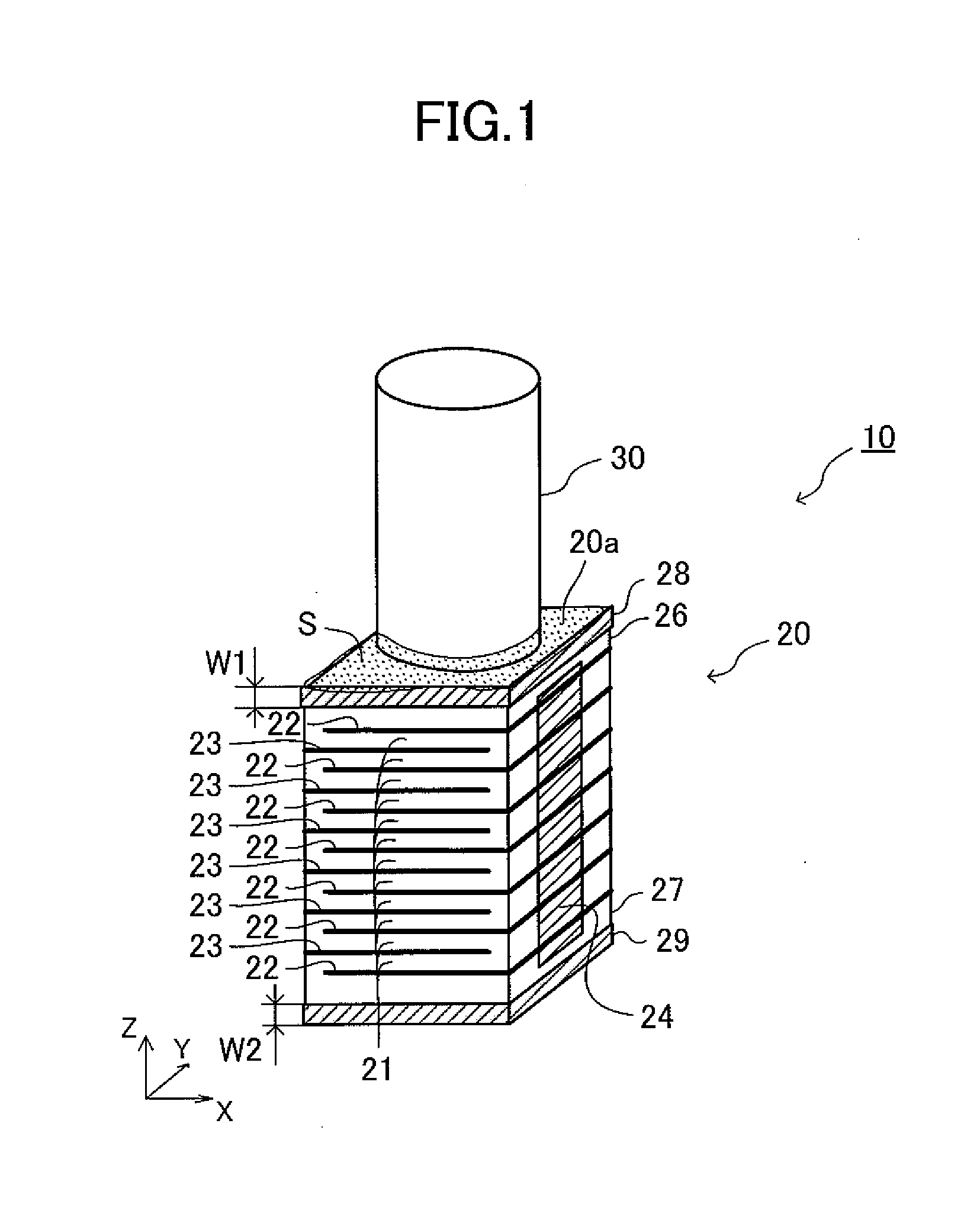
[0041]As shown in FIGS. 1 and 2, the piezoelectric element 20 includes a plurality of piezoelectric layers (layers formed of a piezoelectric material) 21; a plurality of first internal electrode layers 22; a plurality of second internal electrode layers 23; a first side electrode 24; a second side electrode 25; a first end piezoelectric layer 26; a second end piezoelectric layer 27; a dam portion (upper dam portion) 28; and a dam portion (lower dam portion) 29.

[0042]The piezoelectric element 20 has a rectangular parallelepiped shape having edges along the X-axis, the Y-axis, and the Z...

second embodiment

Structure

[0078]As shown in FIG. 3, the electronic device according to the second embodiment of the present invention (hereinafter may be referred to as “the second device”) 40 includes a piezoelectric element (layered piezoelectric element) 50 and a driven member 30. The driven member 30 is the same as the driven member 30 included in the first device 10. The piezoelectric element 50 has a rectangular parallelepiped shape as in the case of the piezoelectric element 20. It should be noted that in the second embodiment, the relationship between each surface (outer surface) of the piezoelectric element 50 and the corresponding coordinate axis is as follows.

[0079]Front side surface: surface at the end (in a negative X-axis direction) of the piezoelectric element 50 and parallel with a Y-Z plane.

[0080]Back side surface: surface at the end (in a positive X-axis direction) of the piezoelectric element 50 and parallel with a Y-Z plane.

[0081]Right side surface: surface at the end (in a negat...


PUM


Abstract

An electronic device 10 includes a layered piezoelectric element 20 and a driven member 30. The driven member 30 is bonded to the top surface 20a of the layered piezoelectric element 20 by means of an epoxy resin adhesive S. The piezoelectric element 20 includes a side electrode 24 on one side surface of the element, which is one of the outer surfaces of the element 20. The piezoelectric element 20 includes, in the vicinity of the upper end portion of the side surface, a dam portion 28 formed of a material for preventing epoxy bleed out of the adhesive S. Therefore, even when the epoxy bleed out of the adhesive S occurs, a bled-out portion of the components of the adhesive S does not reach the side electrode 24. Thus, when the side electrode is connected to an external circuit by, for example, soldering, reduction in the connection strength or similar problems can be avoided.

Description

BACKGROUND OF THE INVENTION[0001]1. Field of the Invention[0002]The present invention relates to an electronic device including an element (e.g., an electric element such as a piezoelectric element or a semiconductor element), and a member which is bonded to the element by means of an epoxy resin adhesive.[0003]2. Background Art[0004]As shown in FIG. 13, a conventional electronic device includes a layered piezoelectric element (element) 100, and a driven member 200 (member other than the element 100) driven by the element 100. The driven member 200 is bonded, by means of an adhesive S, to a top surface 100a of the element 100 (see, for example, Patent Document No. 1).[0005]As used in the present specification, claims, and drawings (hereinafter may be collectively referred to as “the present specification, etc.”), the term “piezoelectric” encompasses “piezoelectric” and “electrostrictive.” Therefore, in the present specification, etc., for example, the term “piezoelectric element” en...

Claims


Application Information

Patent Timeline
IPC IPC(8): H01L41/083H01L41/22H01L41/293H01L41/313
CPCH01L41/0533H01L41/313H01L41/083H10N30/883H10N30/50H10N30/073
Inventor UETANI, MASAYUKITANI, MAKOTO
Owner NGK INSULATORS LTD
Why Eureka
Try Eureka