Immersible oxygen sensor for molten metals

a technology of oxygen sensor and molten metal, which is applied in the field of molten metal immersion probes, can solve the problems of increasing production cost, increasing production time, and inability to consistently provide the quick, accurate, repeatable oxygen content and temperature readings required for today's demanding manufacturing processes, so as to avoid any possible unwanted data distortion, improve production efficiency, and reduce production costs

Inactive Publication Date: 2011-11-10
HENGYANG RAMON SCI & TECH INC LTD
View PDF6 Cites 8 Cited by
  • Summary
  • Abstract
  • Description
  • Claims
  • Application Information

AI Technical Summary

Benefits of technology

[0010]The sand-resin material may include 2 weight % or more of a resin (approximately 5 weight % resin in a preferred embodiment) and approximately 5 weight % ferric oxide. The ferric oxide can alleviate any unwanted RF interference during use of the probe. In accordance with preferred embodiments, no coating nor metal plating is used on the interior of any metal caps used in the vicinity of or in the immersion end of the probe in order to avoid any possible unwanted distortion of the data provided by the probe. However, coatings or metal plating that do not have a deleterious impact on the probe can be used if desired. It is also preferred that there be no holes or openings in any metal caps used.
[0011]In order to avoid the formation of a residual metal ring after the melting of the metal caps, it is preferable to use an irregularly shaped edge or protruding pins are used on the portions of the caps that become embedded in the sand-resin body. In an alternative version of the embodiment, a ledge of sand-resin material is molded onto the face of the probe and acts as a press-fit feature for the metal capping. The presence of this feature prevents the formation of a residual metal ring post immersion. Metal capping systems are mounted without cement and with the irregular shaping or pins at the sand contact area which will avoid formation of round shapes or rings existing after the capping system has melted. An electrical ground consisting of a single point rather than a ring or other structure is greatly preferred.
[0012]In versions that include a sample mold, necessary quick release of the mold and sample from the probe body is enhanced by use of spaces or voids in the sand-resin body or use of a sand-resin blend near the connector end that produces a readily frangible material, for example by reducing the amount of resin in the blend. In embodiments that utilize two different sand blends without employing a void in the sand-resin body, the mating interface between the two sands acts as a fault line or weak point, facilitating removal of the sample. Likewise, metal clips on the mold body are not preferred and are avoided if possible. Release of the mold can also be facilitated by use a larger particle size resin-sand. Any other particulate or fibrous material that is uniformly sized, high temperature, inorganic, gas permeable and moldable may be used. It is important that the exterior and interior of the immersion end of the probe body be free of any cements, sealing compounds, combustibles, moisture and adhesives, all of which might impede the free gas flow into and through and throughout the probe.

Problems solved by technology

Notwithstanding the long history of use of thermocouple and oxygen probes, which sometimes include a metal sampling mold, such probes have heretofore sometimes been subject to fluctuating readings and thus are unable to consistently provide the quick, accurate, repeatable oxygen content and temperature readings required for today's demanding manufacturing processes.
The interruption, pressurization and restraint of the movement of even trace amounts of combustion products or moisture emanating from paperboard or from coatings or materials used in the probe or gases dissolved in the melt and existing in the probe often result in errors in the readings, often causing the need for retesting thereby interrupting and increasing production time and therefore increasing production costs.
To date, combination immersion testing, sampling and oxygen content determining devices have been found to perform with inadequate speed and inconsistent accuracy.

Method used


Image

  • Immersible oxygen sensor for molten metals
  • Immersible oxygen sensor for molten metals
  • Immersible oxygen sensor for molten metals

Examples


Embodiment Construction

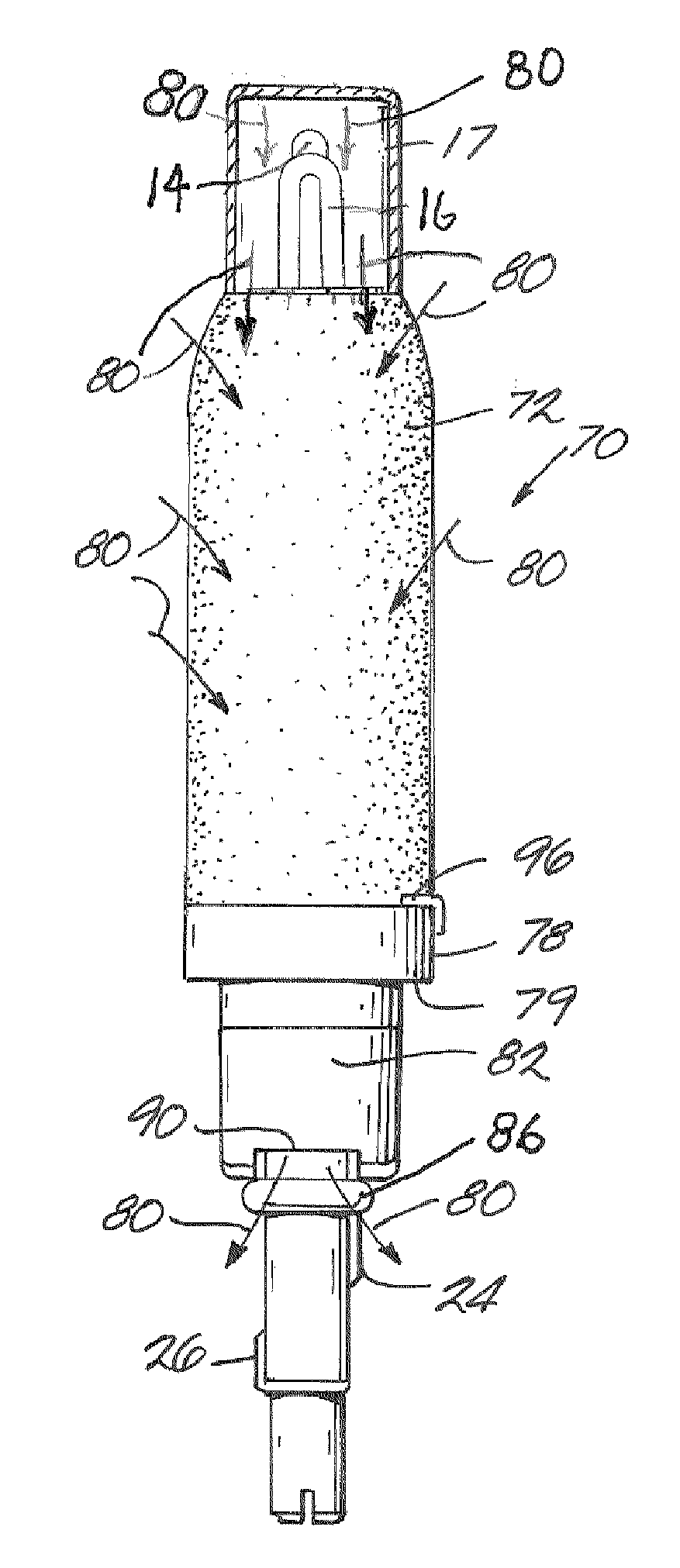
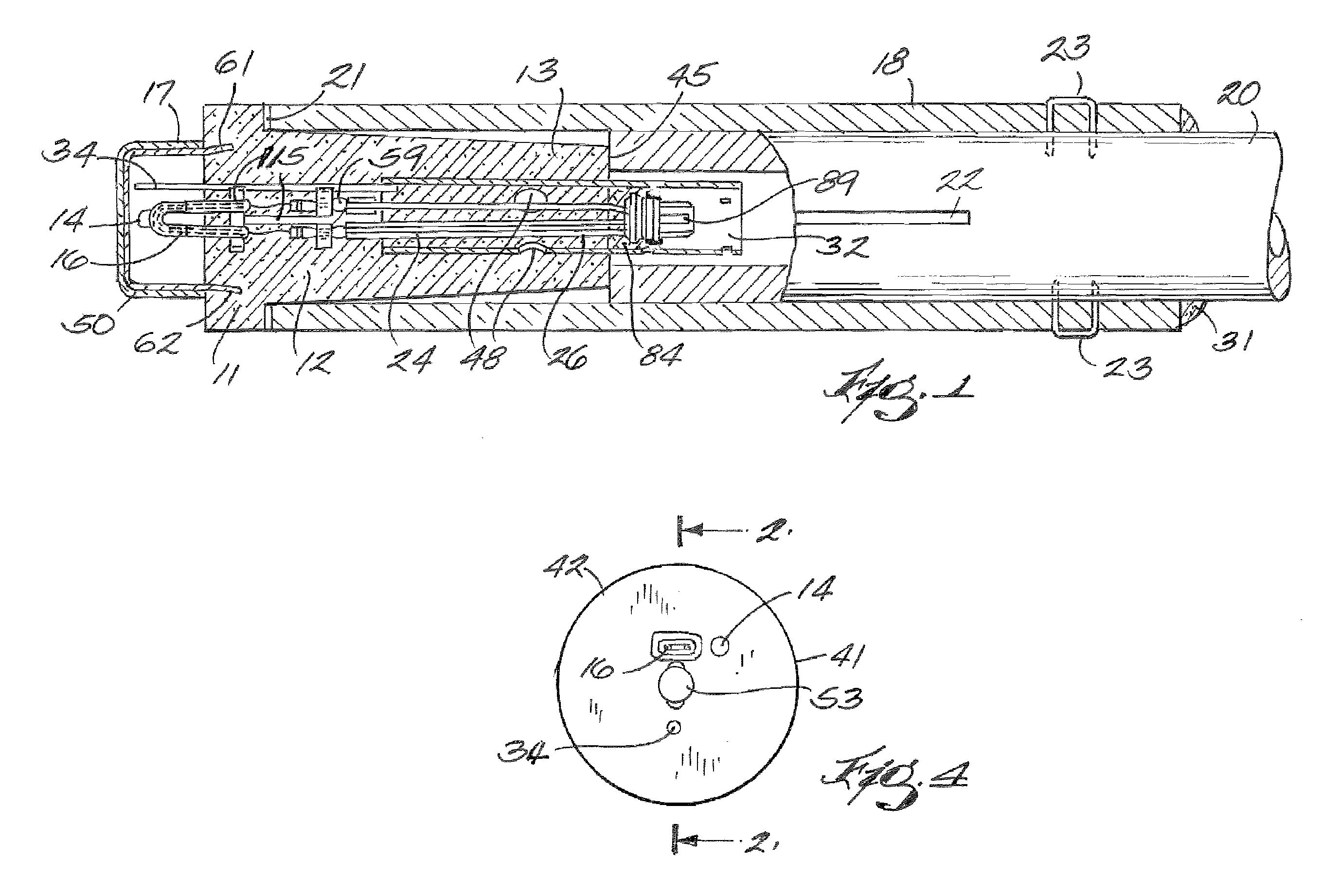
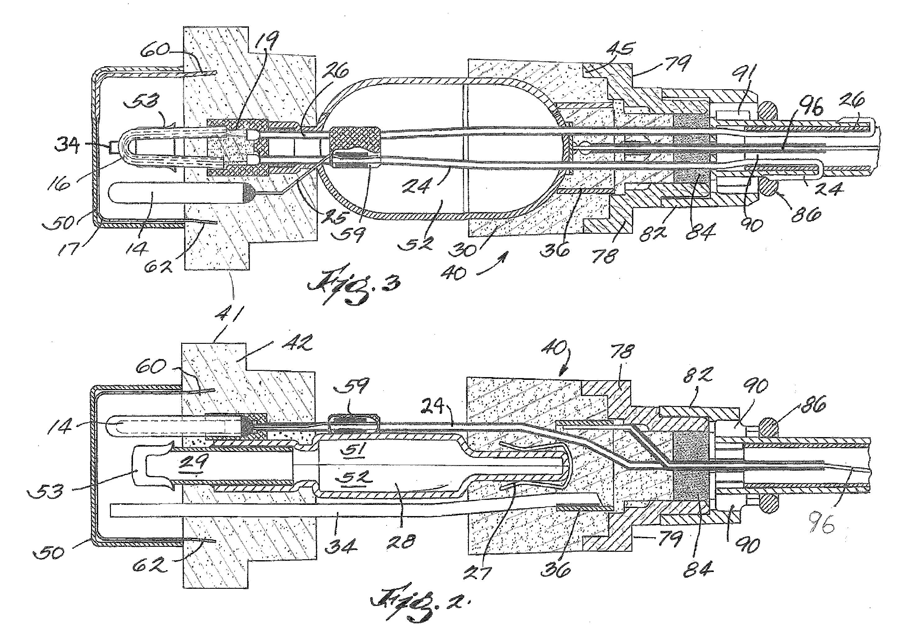
[0022]In accordance with the embodiment of the invention shown in FIG. 1, probe 10 includes a first gas permeable sand-resin, generally cylindrically shaped body 12 formed of a baked gas permeable sand-resin mixture. As shown, the baked sand-resin body 12 has a stem portion 13 of a size adapted to fit within the interior of paperboard sleeve 18 and a radially raised or enlarged portion 11 which serves as a stop for the immersion end of paperboard sleeve 18. The abutting surfaces of the sand-resin body 12 and the end surface 45 of the paperboard sleeve 18 should be totally sealed gas tight. Thus a ceramic cement 21 or the like is used between these abutting surfaces. The end surface 45 is abutted by the end of smaller tube 20 but it is not adhered thereto. Any other sand body contact with the paper tubes 18 or 20 internal to the tubes should not be gas tight. Tubes 18 and 20 are loosely fitted in order to allow gas flow there between. The embodiment of FIG. 1 (as well as FIGS. 6 and ...


PUM

PropertyMeasurementUnit
weight %aaaaaaaaaa
temperatureaaaaaaaaaa

Abstract

An improved immersible oxygen probe for molten metals has a gas permeable body including an immersion end and a support end adapted for being supported by a lance. An oxygen cell and a thermocouple are supported in the immersion end of the body. An unobstructed gas flow passageway is provided through the gas permeable bodies and through the probe body from the immersion end to the support/connector end whereby gases released from the molten metal and sensor body during immersion readily pass through the probe and can escape from within the probe. Thus rapid analysis of the molten metal with improved accuracy within a few seconds after immersion is achieved. The probe contains a sample mold at least partially positioned in an unconfined portion of the permeable body.

Description

[0001]This application is a continuation-in-part of U.S. patent application Ser. No. 13 / 129,678, filed 17 May 2011, claiming priority to PCT Application No. PCT / US09 / 41859, filed 28 Apr. 2009.FIELD OF THE INVENTION[0002]This invention relates to immersible probes for measuring and sampling selected characteristics of molten metal, especially molten iron or steel. The probes are used to measure the temperature and oxygen content of a molten metal and in accordance with some embodiments, are provided with a sample mold so that they may be used to retrieve, simultaneously with those measurements, a representative, high quality sample of the metal for chemical or spectrographic analysis. The probes of this invention can combine all of said devices in a single probe but may include two or even a single measuring device, if desired.BACKGROUND OF THE INVENTION[0003]Immersible oxygen and temperature measuring probes, usually supported for immersion by a molten metal consumable, ablative pap...

Claims


Application Information

Patent Timeline
Patent Type & Authority Applications(United States)
IPC IPC(8): G01N33/20
CPCG01N33/206G01N33/205
Inventor VILLARREAL, V, ASCENCION Z.TURNER, PAUL A.
Owner HENGYANG RAMON SCI & TECH INC LTD
Why Eureka
Try Eureka