
Ortiz turbine

Active Publication Date: 2011-11-10
ORTIZ ISRAEL
View PDF6 Cites 31 Cited by
  • Summary
  • Abstract
  • Description
  • Claims
  • Application Information

AI Technical Summary

Benefits of technology

[0019]In accordance with the present invention, there is provided a turbine that will produce useful mechanical force from the dynamic force of the sea wave. This is done by rectifying the bidirectional force obtained from such wave. This turbine will produce a unidirectional rotation from the bidirectional force of the sea wave. Will do this when placed inside the connecting pipe that connects to a pressure chamber which will produce a bidirectional air flow caused by the variation of water level inside this pressure chamber. The turbine will adjust the pitch of its blades automatically as the air flow inside the pipe changes direction. A normal turbine would rotate back and forward and would be useless in producing output power. The air flow will change the pitch of the blade, because the blade is mounted on a shaft, through ball bearings. Because the blade is acting like a flag with its long tail on a pole, the blade also has a long tail and will always change its direction in accord to the direction of the air flow. Since the pitch can change to a maximum pitch of 45 degrees in both directions it will have a high efficiency.

Problems solved by technology

A normal turbine would rotate back and forward and would be useless in producing output power.

Method used


Image

  • Ortiz turbine
  • Ortiz turbine
  • Ortiz turbine

Examples


Embodiment Construction

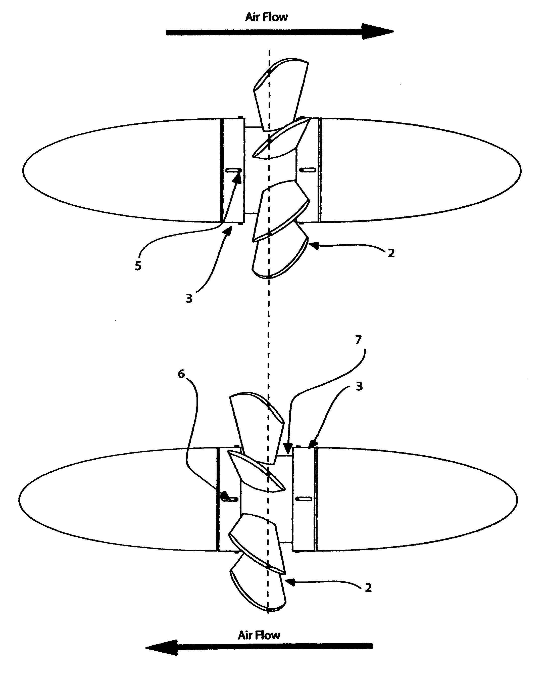
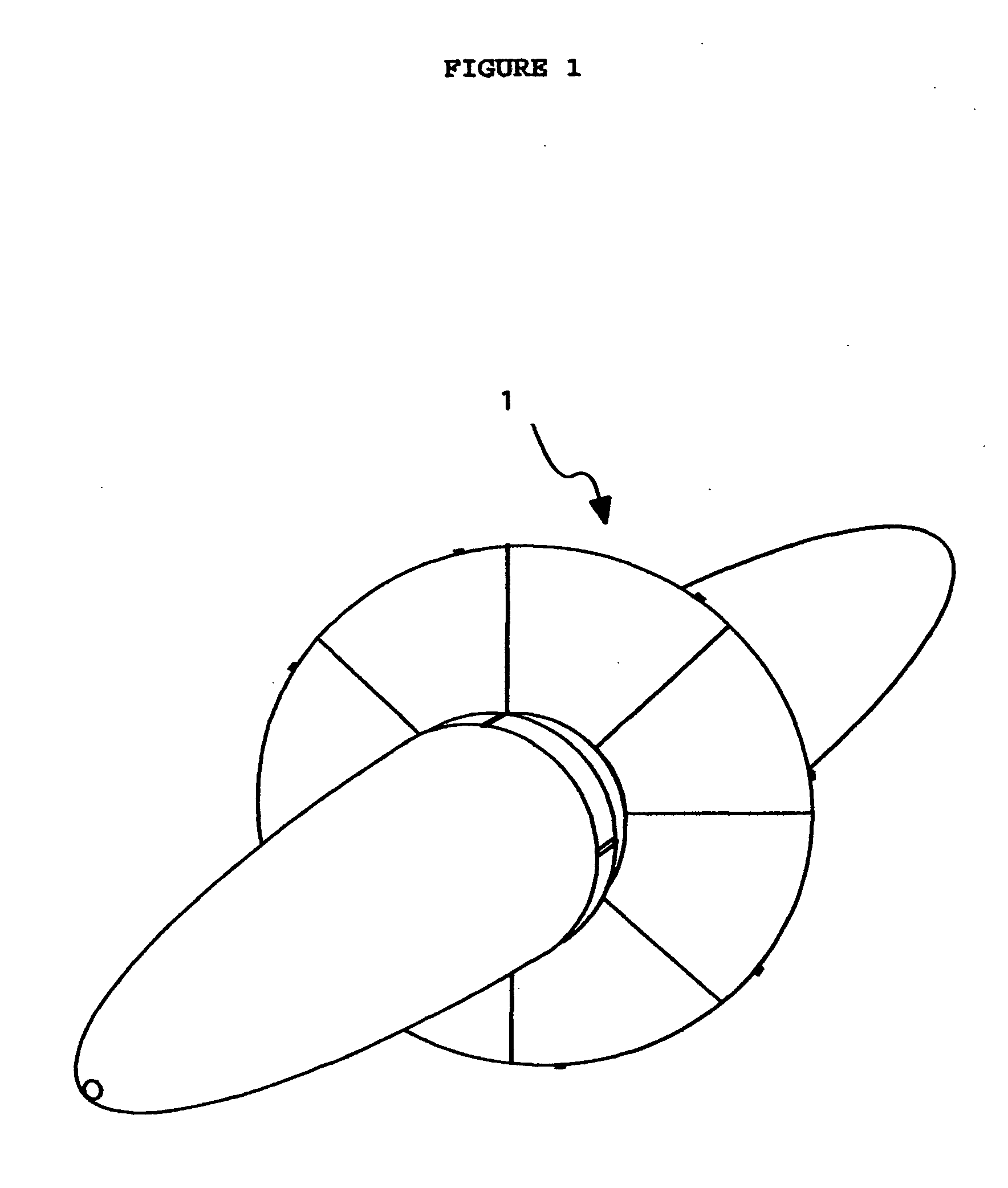
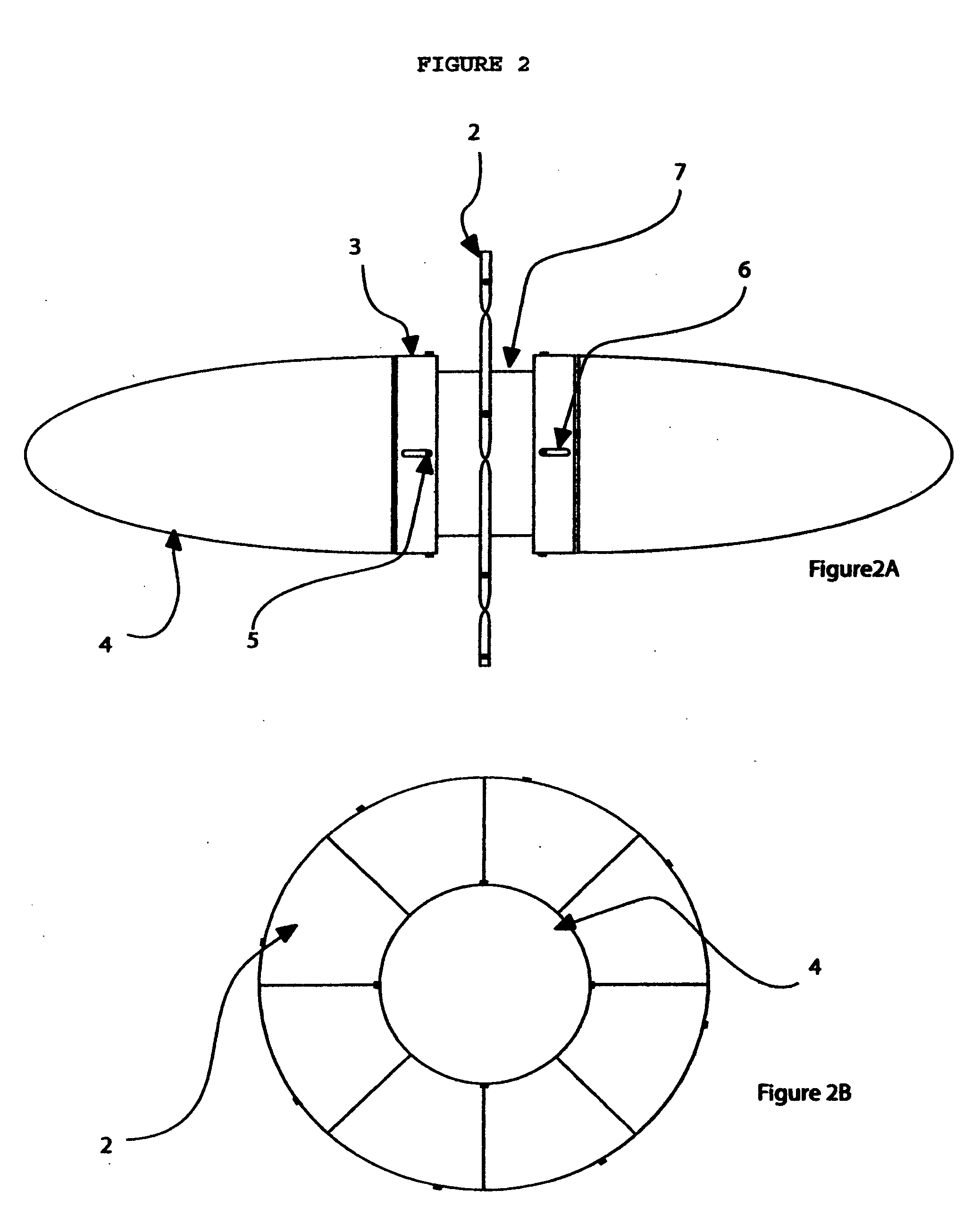
[0031]The Automatic Pitch Turbine 1 seen in FIG. 1 is compose of the following main parts, two pitch adjusting collar 3, two spinner 4, main body 7, blade 2 (or eight blades but could be more or less) which is part of the automatic blade system and main shaft 10, as seen in FIG. 2 and FIG. 3. The plate 9 holds the spinner 4 to the main body 7. The main body 7 holds all the parts together as seen on FIG. 3. In FIG. 4 is seen the parts that compose the automatic pitch system, as fallows, the blade 2, blade shaft 8, two ball bearing 11, one washer 13 and one holding screw 12 that hold all this parts together. Blade hole 14 is where the blade shaft 8 will be inserted into the blade with two ball bearing 11 one on top and one at the bottom. On the blade shaft 8 is where the blade will rotate to change pitch angle.

[0032]The turbine will maintain a unidirectional rotation with a bidirectional flow of gas or liquid. This is done by changing the blade pitch. The air flow is the one that chan...


PUM


Abstract

A turbine that will produce useful mechanical force from the dynamic force of the sea wave. This is done by rectifying the bidirectional force obtained from such wave. This turbine will produce a unidirectional rotation from the bidirectional force of the wave. The turbine will adjust the pitch of its blades automatically as the air flow inside the pipe changes direction, The air flow will change the pitch of the blade, because the blade is mounted on a shaft through ball bearings. Because the blade is acting like a flag on a pole that has a long tail and also the blade has a long tail and will always change its direction in accord to the direction of the air flow.

Description

FIELD OF THE INVENTION[0001]The present invention relates to a turbine and, more particularly, to a bidirectional flow or force turbine, that will turn in one direction with a bidirectional flow or force applied to it.BACKGROUND OF THE INVENTION[0002]The problem with generating power from sea waves, is that the wave is constantly changing its water level. That is, it is changing from crest to trough. This change will produce a force similar to a piston from any engine. When a pipe is use to capture this force, it will produce a force that constantly changing its direction. That is, it is a bidirectional force. A normal turbine would not be able to work with this, because it would constantly be changing the direction of rotation. It would not be able to produce any useful working power.[0003]Therefore, we need a turbine that will always turn in the same direction, no matter the changes in direction of the air flow. Also we need this turbine to be very efficient in doing this. And to ...

Claims


Application Information

Patent Timeline
IPC IPC(8): F03B13/24F01D7/00
CPCF03B3/14F03B13/142Y02E10/223Y02E10/38Y02E10/32F03B13/24Y02E10/20Y02E10/30
Inventor ORTIZ, ISRAEL
Owner ORTIZ ISRAEL
Features
  • Generate Ideas
  • Intellectual Property
  • Life Sciences
  • Materials
  • Tech Scout
  • Unparalleled Data Quality
  • Higher Quality Content
  • 60% Fewer Hallucinations
Learn More