Single-Focus Optical System, Image Pickup Device, and Digital Apparatus

Active Publication Date: 2011-11-10
KONICA MINOLTA OPTO
View PDF9 Cites 101 Cited by
  • Summary
  • Abstract
  • Description
  • Claims
  • Application Information

AI Technical Summary

Benefits of technology

[0092]The single-focus optical system according to the present invention is smaller and has higher performances than the conventional optical system does not adversely affect any other specifications (for example, specifications on F-number and the closest focusing dista

Problems solved by technology

However, since in the conventional configuration, whole three to five lenses are extended altogether, the following problems have become obvious: the size of a drive device is increased, whereby the size of the entire lens unit cannot be reduced; dust generated in a portion havi

Method used


Image

  • Single-Focus Optical System, Image Pickup Device, and Digital Apparatus
  • Single-Focus Optical System, Image Pickup Device, and Digital Apparatus
  • Single-Focus Optical System, Image Pickup Device, and Digital Apparatus

Examples


Example

Example 1

[0214]FIG. 5 is a cross-sectional view showing an arrangement of lens groups in a single-focus optical system of Example 1. FIG. 22 shows aberration diagrams of the single-focus optical system of Example 1. FIG. 22 shows the infinite case. The above description is applied to Example 2-Example 17 to be described later (FIG. 6-FIG. 21 and FIG. 23-FIG. 38).

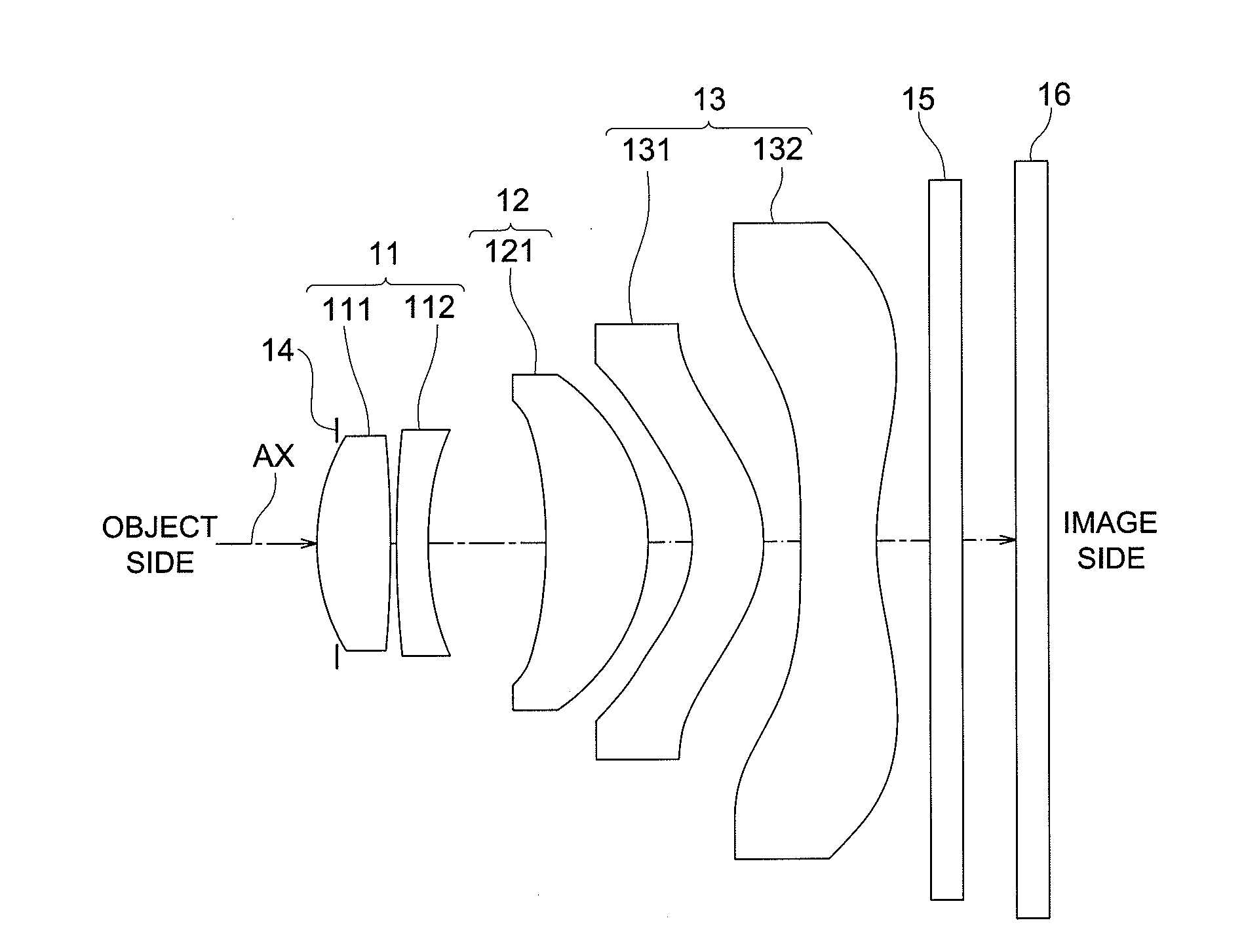
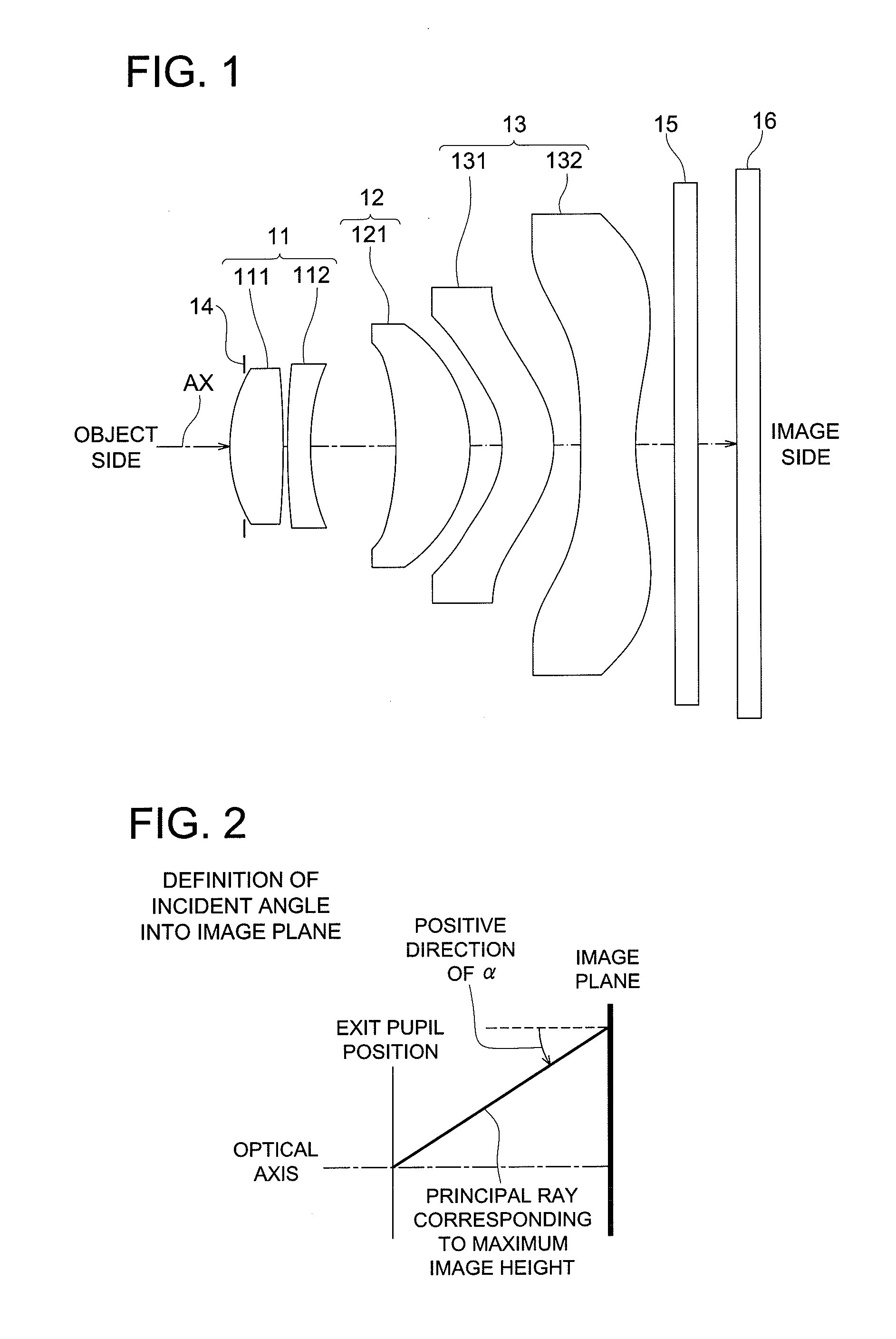
[0215]In the single-focus optical system 1A of Example 1, each of the lens groups (Gr1, Gr2, and Gr3) is arranged in order from the object side to the image side as shown in FIG. 5, and when focusing (focus adjustment) is performed, the first lens group (Gr1) is fixed with respect to a predetermined imaging surface; the second lens group (Gr2) is moved in the optical axis AX direction; and the third lens group (Gr3) is fixed with respect to the predetermined imaging surface.

[0216]Since such an optical system employing an inner-focusing system has a mechanism for moving in an optical axis direction for focus adjustment, the n...

Example

Example 2

[0241]FIG. 6 is a cross-sectional view showing an arrangement of lens groups in a single-focus optical system of Example 2. FIG. 23 shows aberration diagrams of the single-focus optical system of Example 2.

[0242]In the single-focus optical system 1B of Example 2, each of the lens groups (Gr1, Gr2, and Gr3) is arranged in order from the object side to the image side as shown in FIG. 6, and when focusing is performed, the first lens group (Gr1) is fixed with respect to a predetermined imaging surface; the second lens group (Gr2) is moved in the optical axis AX direction; and the third lens group (Gr3) is fixed with respect to the predetermined imaging surface.

[0243]In more details, in the single-focus optical system 1B of Example 2, the lens groups (Gr1, Gr2, and Gr3) are constituted in order from the object side to the image side as described below.

[0244]The first lens group (Gr1) is constituted of a biconvex positive lens (a first lens L1) and a negative meniscus lens (a se...

Example

Example 3

[0254]FIG. 7 is a cross-sectional view showing an arrangement of lens groups in a single-focus optical system of Example 3. FIG. 24 shows aberration diagrams of the single-focus optical system of Example 3.

[0255]In the single-focus optical system 1C of Example 3, each of the lens groups (Gr1, Gr2, and Gr3) is arranged in order from the object side to the image side as shown in FIG. 7, and when focusing is performed, the first lens group (Gr1) is fixed with respect to a predetermined imaging surface; the second lens group (Gr2) is moved in the optical axis AX direction; and the third lens group (Gr3) is fixed with respect to the predetermined imaging surface.

[0256]In more details, in the single-focus optical system 1C of Example 3, the lens groups (Gr1, Gr2, and Gr3) are constituted in order from the object side to the image side as described below.

[0257]The first lens group (Gr1) is constituted of a biconvex positive lens (a first lens L1), an aperture stop ST, and a negati...


PUM


Abstract

Provided is a single-focus optical system which is configured, in order from the object side to the image side, of a first to third lens groups and in which the first lens group and the third lens group are fixed with respect to a predetermined imaging surface, and the second lens group is moved in the optical axis direction to focus, wherein the first lens group comprises at least one positive lens and at least one negative lens, the second lens group comprises at least one positive lens, the third lens group comprises at least one lens having at least one aspheric surface and having a positive optical power at a peripheral portion thereof, and 5<|Δv1|<70 is satisfied where Δv1 is a maximum value of the Abbe number difference between the positive lens and the negative lens in the first lens group.

Description

TECHNICAL FIELD[0001]The present invention relates to a single-focus optical system, and specifically to a single-focus optical system preferably applied to a solid-state imaging element such as a CCD image sensor or a CMOS image sensor. In addition, the present invention relates to an image pickup device provided with the single-focus optical system, and to a digital apparatus mounted with the image pickup device.BACKGROUND[0002]Over recent years, with advance of higher performance and further downsizing of imaging elements using solid-state imaging elements such as CCD (Charge Coupled Device)-image sensors or CMOS (Complementary Metal Oxide Semiconductor) image sensors, mobile phones and portable information terminals provided with an image pickup device using such an imaging element are prevailing. Further, in imaging lenses (imaging optical systems) installed in these image pickup devices, there is an increasing demand for further downsizing and higher performances. For an imagi...

Claims


Application Information

Patent Timeline
IPC IPC(8): H04N5/232G02B13/18
CPCG02B13/0045
Inventor MATSUSAKA, KEIJIWAKIMURA, TAIZOISONO, MASASHISANO, EIGOYAMADA, KEIKOTANAKA, HIROAKI
Owner KONICA MINOLTA OPTO
Why Eureka
Try Eureka