High power and high gain fiber amplifier

a fiber amplifier, high-power technology, applied in the direction of optical elements, instruments, semiconductor lasers, etc., can solve the problems of more complex and costly fabrication, and achieve the effects of high output power, high efficiency, and high gain

Inactive Publication Date: 2011-11-10
UNITED STATES OF AMERICA THE AS REPRESENTED BY THE SEC OF THE ARMY
View PDF20 Cites 13 Cited by
  • Summary
  • Abstract
  • Description
  • Claims
  • Application Information

AI Technical Summary

Benefits of technology

[0010]The invention uses a simple 2-stage amplifier structure that relies on a single 2×2 double cladding fiber coupler. The coupler design allows uneven splitting of the pump power between the two coupler fibers and makes it possible to transfer most of the pump power from one fiber into the second fiber. The 2-stage amplifier uses a single, high power pump diode to pump both gain stages, with pump power apportioned optimally between the stages. The configuration achieves high gain, high efficiency and high output power with minimum number of components, thereby minimizing amplifier complexity, size, and cost. Since the pump diode is typically the highest cost component in a fiber amplifier, the use of a single high power broad area pump diode to pump both amplifier stages makes it possible to achieve high amplifier gain concurrently with high average output. Since different double cladding fibers can be used in the two amplification stages, each double cladding fiber can be chosen to optimize the operation of the particular gain stage. Other techniques that utilize double cladding fiber couplers require use of multiple couplers to assemble a multi-stage fiber amplifier, and therefore are more complex and costly to fabricate.

Problems solved by technology

Other techniques that utilize double cladding fiber couplers require use of multiple couplers to assemble a multi-stage fiber amplifier, and therefore are more complex and costly to fabricate.

Method used


Image

  • High power and high gain fiber amplifier
  • High power and high gain fiber amplifier
  • High power and high gain fiber amplifier

Examples


Embodiment Construction

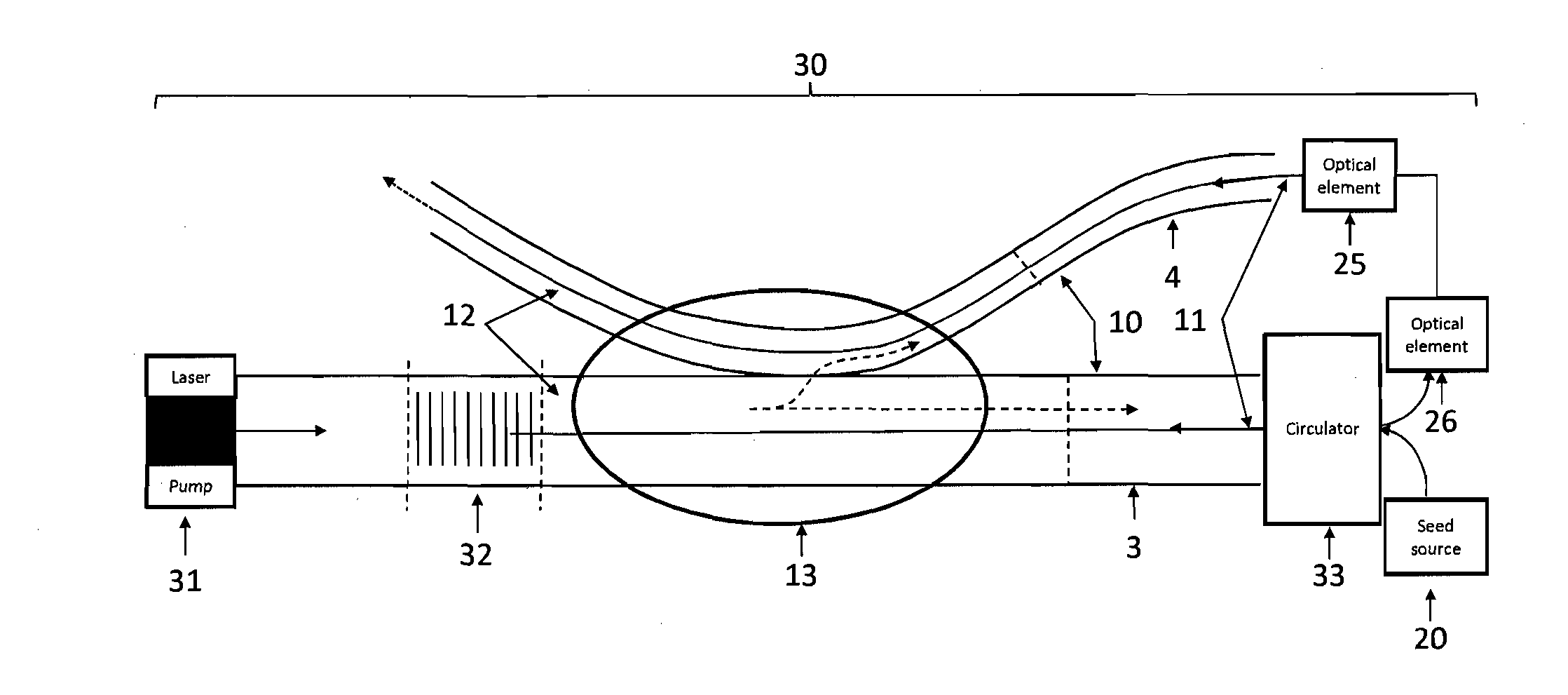
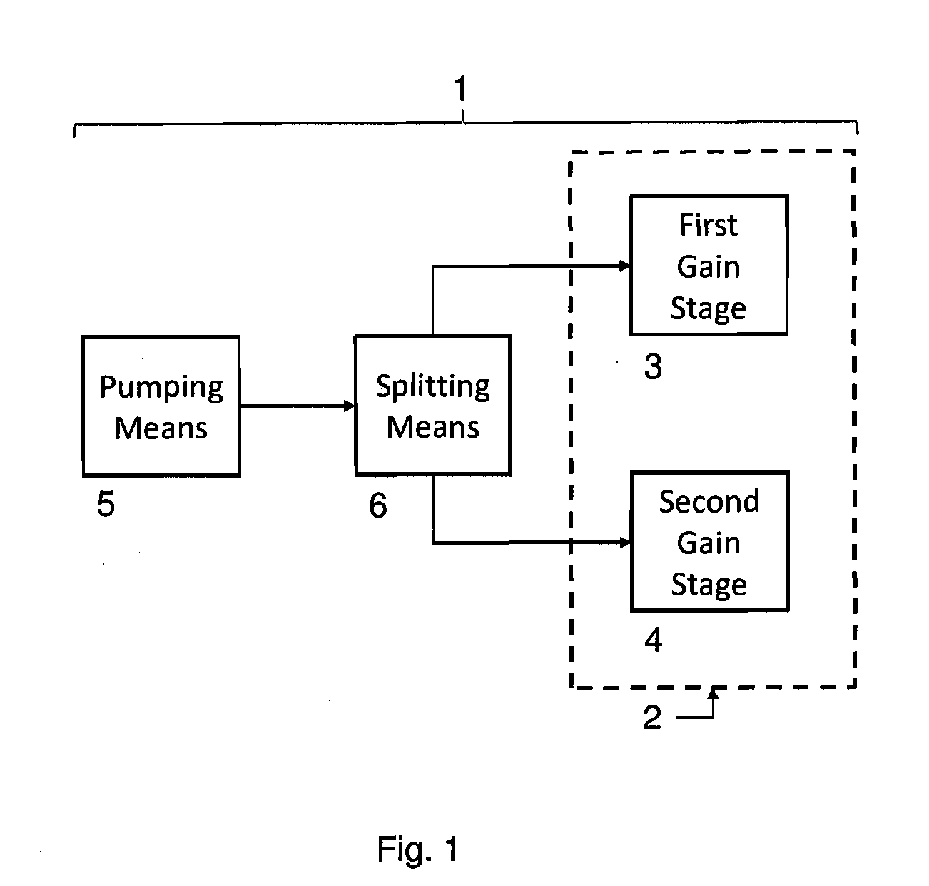
[0018]Referring now to the drawings, where like reference numerals designate identical or corresponding parts, FIG. 1 is a block diagram of the device 1 for amplifying signals propagating in optical fibers in accordance with the invention. The amplifying device comprises a double cladding fiber amplifier 2 having two gain stages 3 and 4, pumping means 5 for coupling pump light into the double cladding fiber amplifier, and splitting means 6 for splitting the coupled pump light 14 between the two gain stages of the double cladding fiber amplifier.

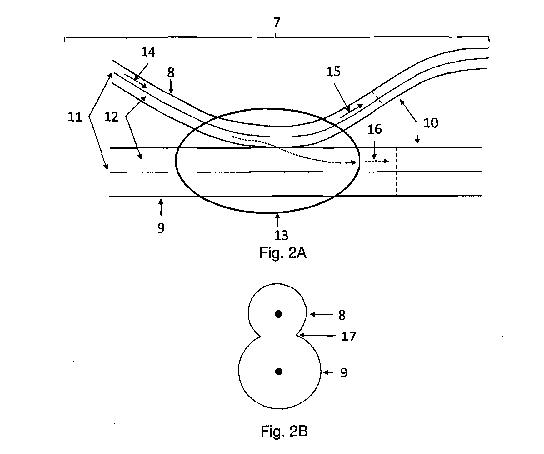
[0019]While the splitting means 6 may take a variety of forms, conveniently it may take the form shown in FIG. 2 of a fiber coupler 7 made up of two double cladding fibers 8 and 9. The two double cladding fibers are fused together in the coupling region 13 or are in optical contact with each other to allow power transfer to occur from one cladding into the other. The fiber coupler 7 is fabricated so that a sufficiently strong optical coupling...


PUM


Abstract

A device for amplifying optical signals propagating in optical fibers comprising a double cladding fiber amplifier having multiple gain stages, a port for coupling pump light into the double cladding fiber amplifier, and a double cladding fiber coupler for splitting the coupled pump light between the gain stages of the double cladding fiber amplifier. Also, a method for amplifying optical signals propagating in optical fibers comprising the steps of providing a double cladding fiber amplifier having multiple gain stages, coupling pump light into the double cladding fiber amplifier, and splitting the coupled pump light between the gain stages of the double cladding fiber amplifier.

Description

GOVERNMENT INTEREST[0001]The invention described herein may be manufactured, used, sold, imported, and / or licensed by or for the Government of the United States of America.FIELD OF THE INVENTION[0002]This invention relates in general to fiber optic devices, and more particularly to optical fiber amplifiers.BACKGROUND OF THE INVENTION[0003]In the past, multi-stage amplifiers have been used to achieve the high optical signal gain needed to amplify signals propagating in optical fibers. In a single stage optical amplifier, the overall optical signal gain is limited by the buildup of amplified spontaneous emission which clamps the maximum population inversion that can be achieved in the active dopant in the fiber core (typically Er, Yb, Er / Yb, Nd, Tm). The buildup of amplified spontaneous emission can be suppressed by placing several elements between the amplification stages. These include optical isolators to eliminate backward propagating amplified spontaneous emission, narrow-band sp...

Claims


Application Information

Patent Timeline
Patent Type & Authority Applications(United States)
IPC IPC(8): H01S3/067
CPCH01S3/06737H01S3/06758H01S3/09415H01S3/094061H01S3/094007H01S5/2036
Inventor GOLDBERG, LEW
Owner UNITED STATES OF AMERICA THE AS REPRESENTED BY THE SEC OF THE ARMY
Why Eureka
Try Eureka