Heat dissipation system with a spray cooling device

a technology of heat dissipation system and cooling device, which is applied in the direction of lighting and heating apparatus, semiconductor/solid-state device details, and domestic cooling apparatus, etc. it can solve the problems of reducing the overall heat dissipation effect, increasing the temperature of working fluid, and not meeting the requirement for dissipating heat generated by high-powered electronic components. , to achieve the effect of high heat dissipation efficiency and simple construction

Inactive Publication Date: 2011-11-17
MICRO BASE TECH CORP
View PDF13 Cites 41 Cited by
  • Summary
  • Abstract
  • Description
  • Claims
  • Application Information

AI Technical Summary

Benefits of technology

[0007]An object of the present invention is to provide a heat dissipatio

Problems solved by technology

An ordinary active-type heat-dissipating system for electronic components such as a fan incorporated with fins, a fan incorporated with fins and heat-transmitting ducts, etc., usually faces a problem of insufficient unit area heat flux and hence cannot meet the requirement for dissipati

Method used


Image

  • Heat dissipation system with a spray cooling device
  • Heat dissipation system with a spray cooling device
  • Heat dissipation system with a spray cooling device

Examples


Embodiment Construction

[0022]Before the present invention is described in greater detail with reference to the accompanying preferred embodiments, it should be noted herein that like elements are denoted by the same reference numerals throughout the disclosure.

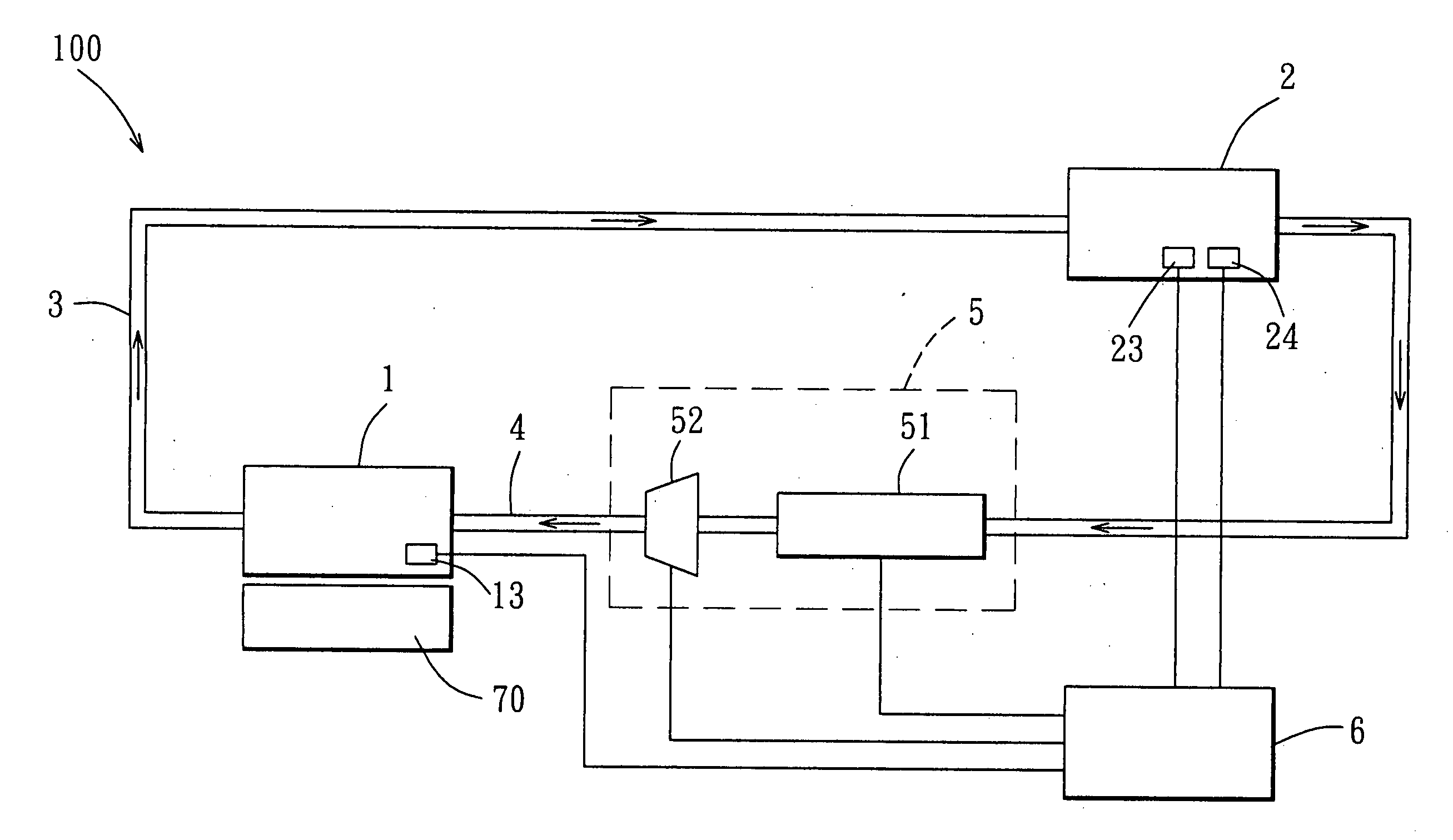
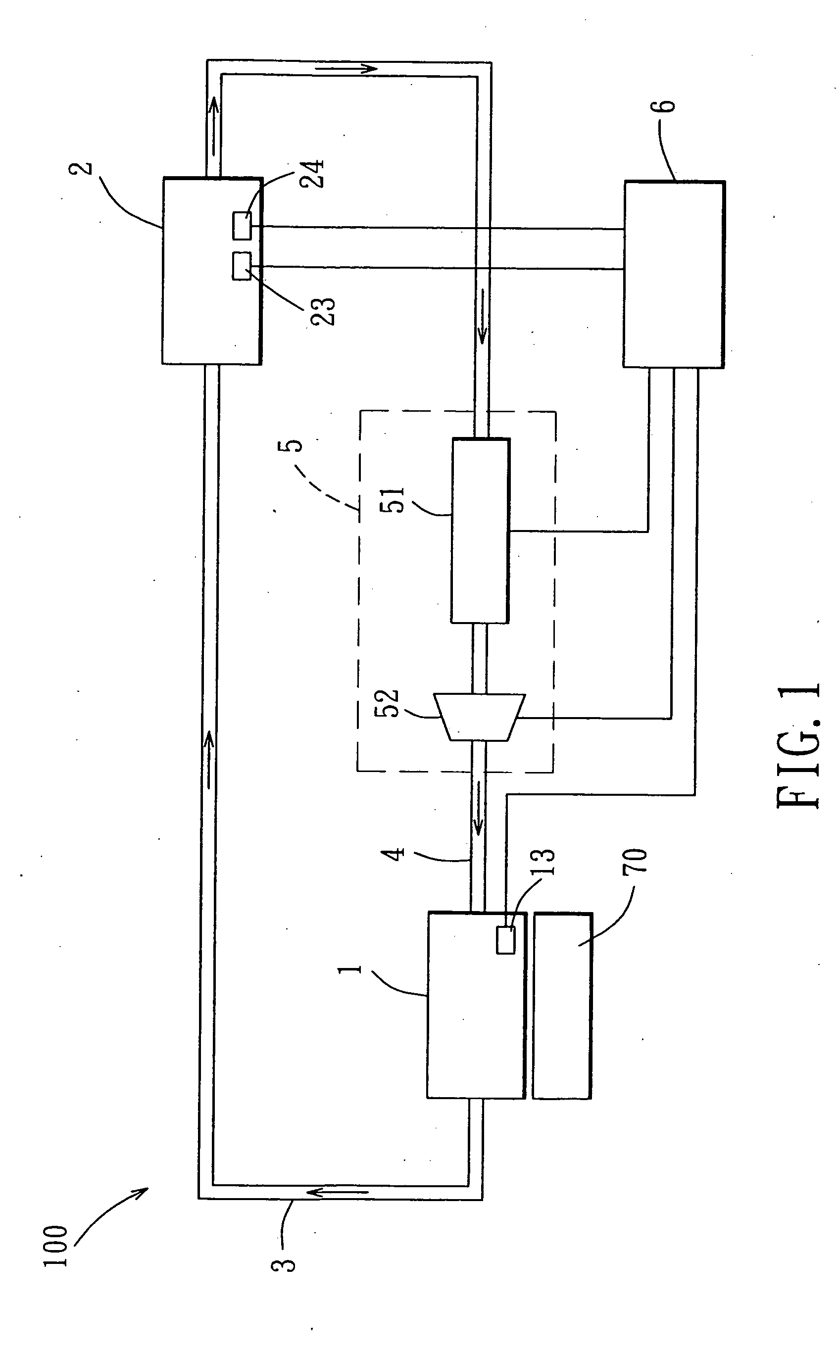
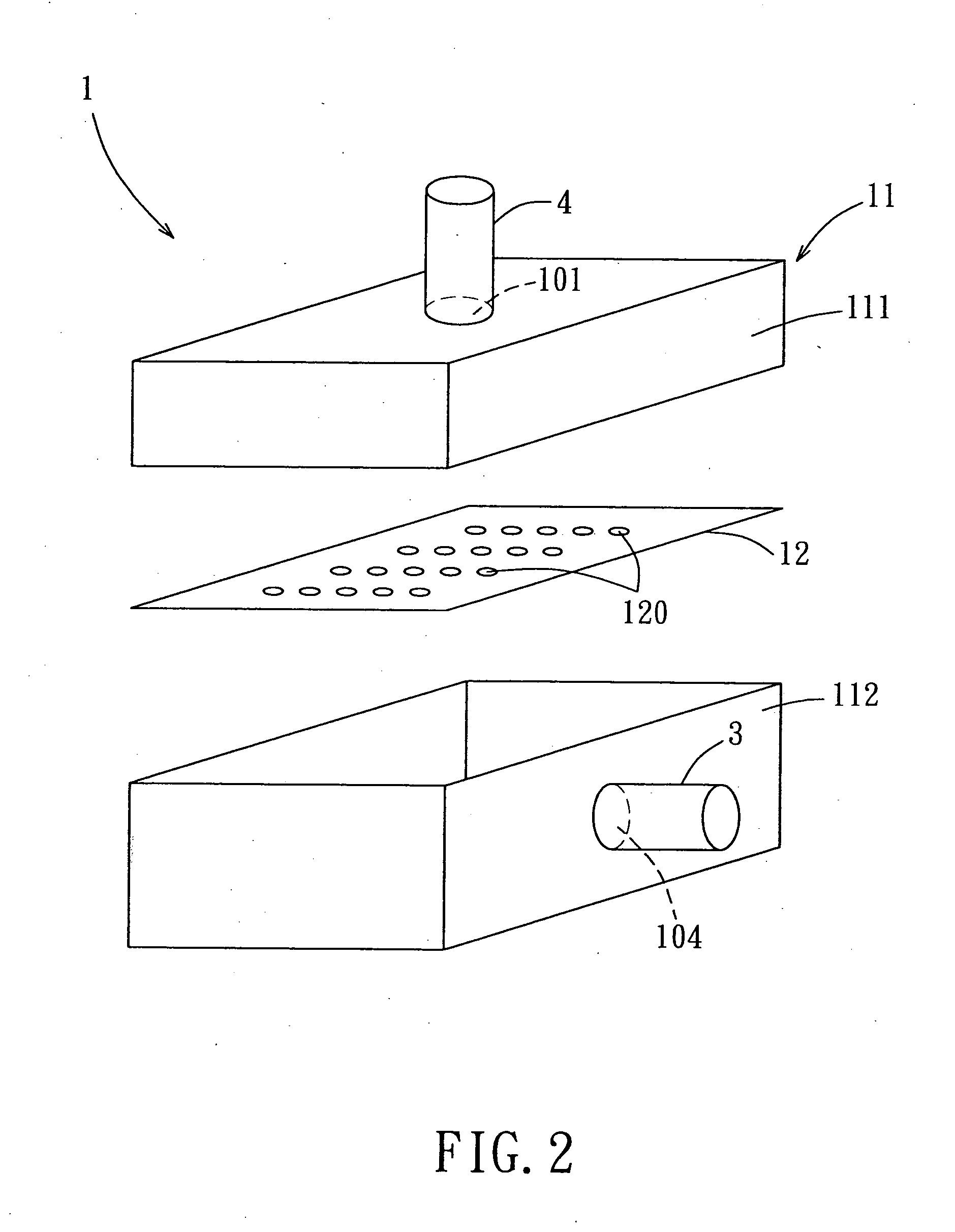
[0023]Referring to FIG. 1, there is shown a cooling system 100 according to the first preferred embodiment of the present invention for dissipating heat generated by a heat source 70. The cooling system includes a cooling device 1, a condenser 2, a vapor conveying duct 3, a cooling liquid conveying duct 4, a fluid driving module 5 and a power and control module 6. The cooling device 1, the condenser 2, the vapor conveying duct 3 and the cooling liquid conveying duct 4 cooperate to form a closed circuit. The fluid driving module 5 has a pump 51 connected to the closed circuit for driving a working fluid, and a control valve 52 connected to the closed circuit for controlling the working fluid. In this embodiment, the working fluid is one of the Flouri...


PUM


Abstract

A heat dissipation system includes a cooling device, a condenser, a vapor conveying duct and a cooling liquid conveying duct. The cooling device includes a housing, and an orifice plate dividing an inner space of the housing into a liquid supply chamber and an evaporation chamber proximate to the heat source, and formed with multiple micro orifices each having a diameter ranging from 5 to 1000 micrometers. The condenser includes a fluid inlet, a condensing chamber and a fluid outlet. The vapor conveying duct connects a vapor outlet of the housing and the fluid inlet of the condenser. The cooling liquid conveying duct connects a cooling liquid inlet of the housing and a fluid outlet of the condenser.

Description

CROSS REFERENCE TO RELATED APPLICATION[0001]This application claims priority of Taiwanese application no. 99104710 filed on Feb. 12, 2010.BACKGROUND OF THE INVENTION[0002]1. Field of the Invention[0003]The invention relates to a heat dissipation system, and more particularly to a closed-loop heat dissipation system that employs a principle of a liquid-vapor phase change.[0004]2. Description of the Related Art[0005]An ordinary active-type heat-dissipating system for electronic components such as a fan incorporated with fins, a fan incorporated with fins and heat-transmitting ducts, etc., usually faces a problem of insufficient unit area heat flux and hence cannot meet the requirement for dissipating heat generated by high-powered electronic components.[0006]To meet the requirement for dissipating heat generated by high-powered electronic components, in recent years, heat dissipation technique employing operating principles of liquid-vapor phase change have been developed. For example...

Claims


Application Information

Patent Timeline
IPC IPC(8): F28D5/00F25D17/00
CPCH01L23/4336H01L23/473H01L2924/0002H01L2924/00F28D15/0266F28D15/046F28F9/026
Inventor WU, CHING-PINGCHENG, KAI-ANWU, CHUN-HSIENLIN, JU-HONGLIAO, CHIA-CHENMENG, HSIENMENG, HSIEN-CHUN
Owner MICRO BASE TECH CORP
Why Eureka
Try Eureka