
Engine structure having conjugate cam assembly

Inactive Publication Date: 2011-11-17
NAT SUN YAT SEN UNIV
View PDF6 Cites 7 Cited by
  • Summary
  • Abstract
  • Description
  • Claims
  • Application Information

AI Technical Summary

Benefits of technology

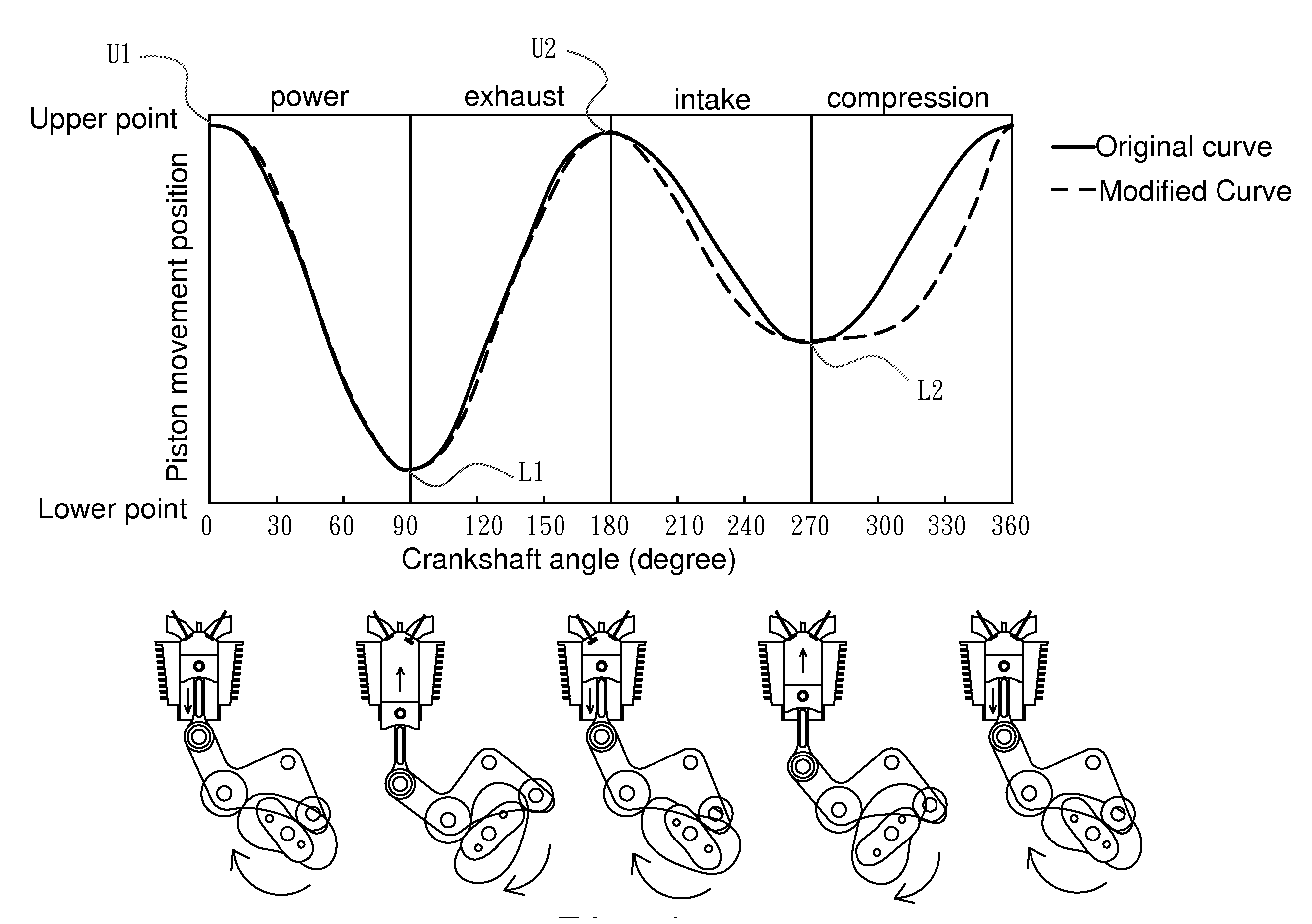
[0009]A primary object of the present invention is to provide an engine structure having conjugate cam assembly, which has a piston used to push or pulled by a conjugate cam assembly mounted on a camshaft through a connection rod, a roller rocker and two rollers, wherein the conjugate cam assembly has two cams with cam profiles and relative arrangement angle which can be varied according to actual operational desire, so as to vary the ratio of intake / exhaust strokes and the ratio of compression / power strokes. Thus, the combustion efficiency and the exhaustion efficiency can be enhanced, while the power output can be enhanced.
[0010]A secondary object of the present invention is to provide an engine structure having conjugate cam assembly, which has a piston used to push or pulled by a conjugate cam assembly mounted on a camshaft through a connection rod, a roller rocker and two rollers, wherein the camshaft only rotates one circle (i.e. 360 degree) when the piston finishes four strokes of an operational cycle. Thus, the variation range of rotation speed of the camshaft can be narrowed, the operational loading of the camshaft can be reduced, the component abrasion of external mechanism can be decreased, and the entire volume of the engine can be minimized.

Problems solved by technology

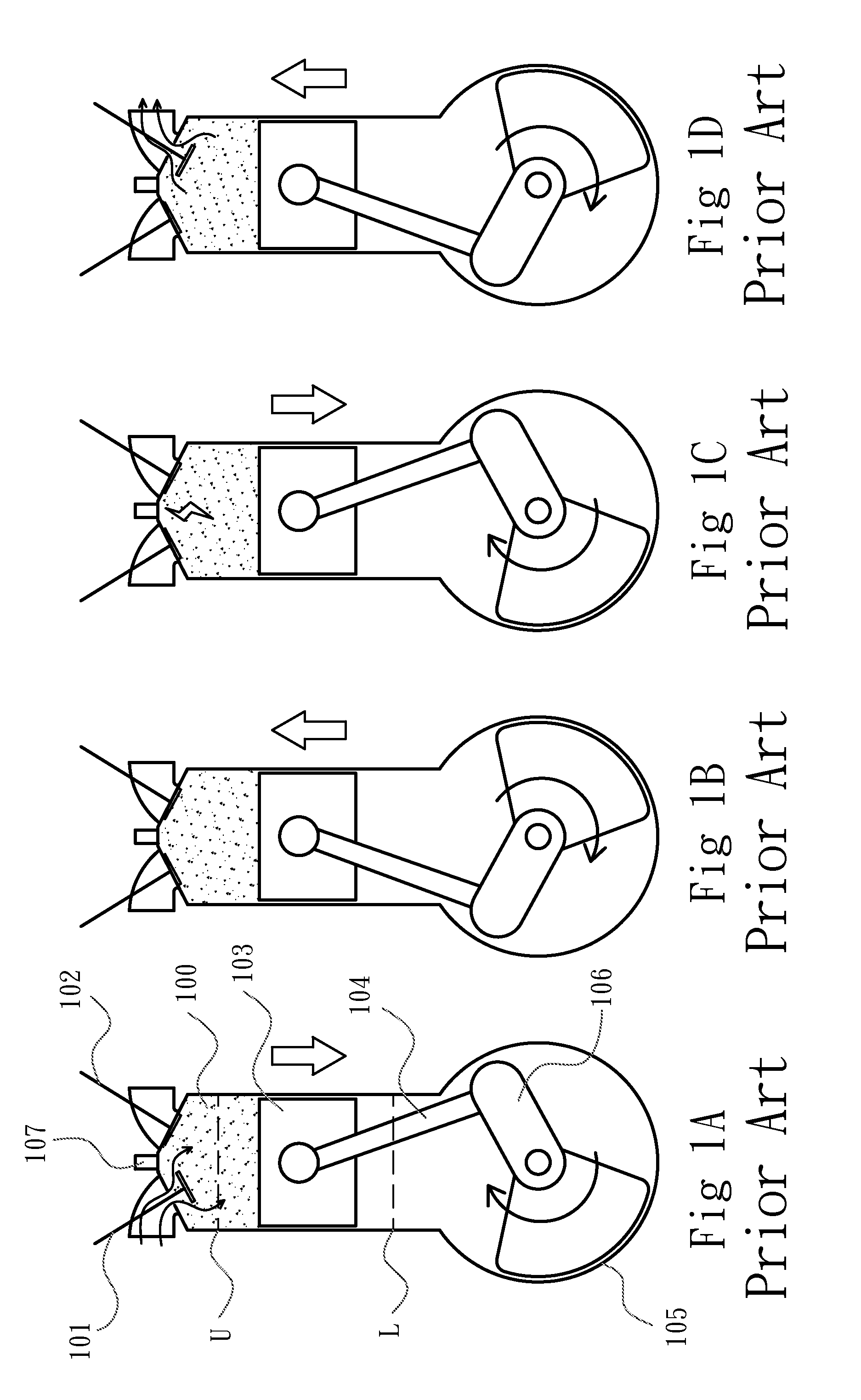
However, there are some technical problems existing in the traditional four-stroke type engine, as follows: In the exhaust stroke, some portion of the exhaust gas is generally remained in the cylinder 100 after finishing the previous operation cycle, so that the remained the exhaust gas affects the efficiency of the intake stroke and the power stroke of the next operation cycle.
If the displacement of the piston 103 in the intake stroke, the compression stroke, the power stroke and the exhaust stroke is equal to each other, the ratio of the intake and exhaust volume can not be adjusted, so that the problem of the remained exhaust gas can not be solved.
In addition, the crankshaft 106 must rotate one circle to finish the intake stroke and the compression stroke, but the crankshaft 106 can not output any effective power to drive the external mechanism at this time.
As a result, there is a problem of discontinuous acceleration between the first circle and the second circle of the crankshaft 106.
It causes that the traditional four-stroke type engine is not suitably applied to a high-speed rotation condition.
However, this arrangement increases the entire volume of the engine, so that it is disadvantageous to reduce the occupied space of the engine.

Method used


Image

  • Engine structure having conjugate cam assembly
  • Engine structure having conjugate cam assembly
  • Engine structure having conjugate cam assembly

Examples


Embodiment Construction

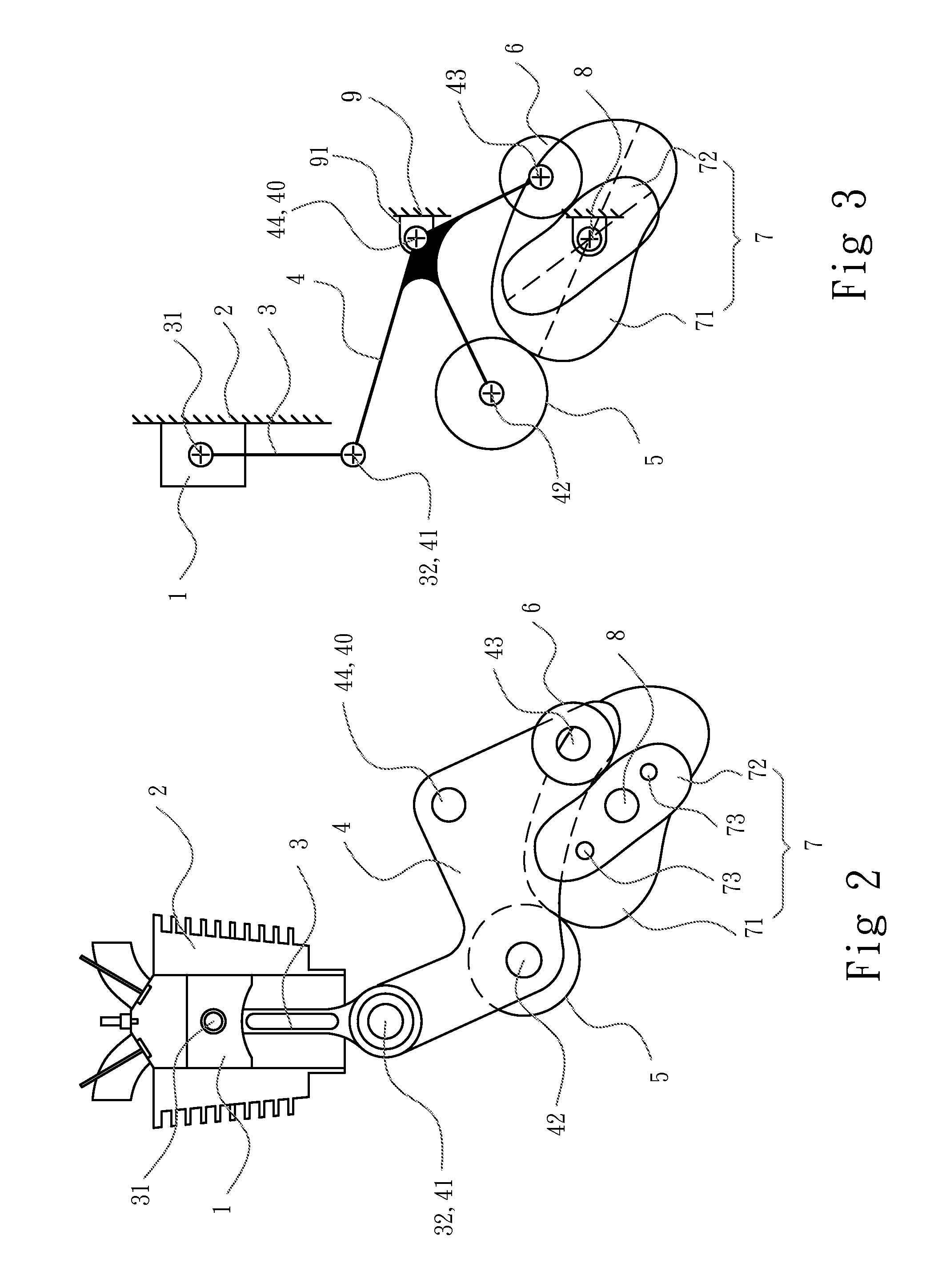
[0033]Referring now to FIGS. 2 and 3, an engine structure having conjugate cam assembly according to a first embodiment of the present invention is illustrated. As shown, the engine structure having conjugate cam assembly is a four-stroke type engine structure which is mainly applied to various industrial applications, such as vehicles (including automobiles or motorcycles) or generators, but not limited thereto. The engine structure of the present invention comprises a piston 1, a cylinder 2, a connection rod 3, a roller rocker 4, a push roller 5, a pull roller 6, a conjugate cam assembly 7 and a camshaft 8 (also called power shaft or crankshaft), all of which is basically made of metal, alloy or ceramic material, such as aluminum, aluminum alloy, stainless steel or alumina ceramic, but not limited thereto. It should be noted that directional terms (such as upper, lower, left, right, inner, outer, longitudinal, transverse and etc.) of the present invention described hereinafter are...


PUM


Abstract

An engine structure having a conjugate cam assembly is provided and includes a piston which can be used to push or pulled by the conjugate cam assembly mounted on a camshaft through a connection rod, a roller rocker and two rollers. The conjugate cam assembly has two cams with cam profiles and relative arrangement angle which can be varied according to actual operational desire, so as to vary the ratio of intake / exhaust strokes and the ratio of compression / power strokes. Thus, the combustion efficiency and the exhaustion efficiency can be enhanced. When the camshaft finishes four strokes of an operational cycle, the camshaft only rotates one circle (i.e. 360 degree), so that the rotation speed of the camshaft can be lowered.

Description

FIELD OF THE INVENTION[0001]The present invention relates to an engine structure having a conjugate cam assembly, and more particularly to an engine structure having a camshaft which can finish four strokes in one operational cycle through a conjugate cam assembly that can be further used to adjust the ratio of intake / exhaust strokes.BACKGROUND OF THE INVENTION[0002]An engine is used to mix a fuel with the air into a combustible mixture gas, and then guide the mixture gas into a cylinder, followed by sparking the mixture gas through a spark plug to cause the combustion of the mixture gas, so as to actuate a piston to reciprocally move in the cylinder. Then, the piston actuates a crankshaft through a connection rod, so that the crankshaft can be used to drive an external mechanism. Generally, the engine is applied to various industrial applications, such as vehicles (including automobiles or motorcycles) or generators, wherein the common engines can be classified into two-stroke type...

Claims


Application Information

Patent Timeline
IPC IPC(8): F02B75/04F02B75/32
CPCF01B9/06F02B41/04F02B75/045Y10T74/2184F02B75/04F02B75/048Y10T74/2173F02B75/32
Inventor TSAY, DER-MINCHEN, HSIN-PAOCHENG, TING-HAO
Owner NAT SUN YAT SEN UNIV
Learn More