Heat Exchanger Tank and Related Methods and Apparatuses

a technology of heat exchanger and tank, which is applied in the direction of indirect heat exchanger, machines/engines, lighting and heating apparatus, etc., can solve the problems of plastic tanks, aluminum side brackets that lack the strength and cost advantages of steel side brackets, and tend to be less durable, so as to facilitate the connection of the tanks and facilitate the insertion of the radiator tanks

Active Publication Date: 2011-11-17
RICHARDSON COOLING PACKAGES
View PDF3 Cites 13 Cited by
  • Summary
  • Abstract
  • Description
  • Claims
  • Application Information

AI Technical Summary

Benefits of technology

[0016]In a still further embodiment, the present disclosure relates to an all-aluminum (or aluminum alloy) industrial heat exchanger (or radiator) that provides consistency in tank-to-header joint locations to allow use of robotic welding of tanks to headers. A header design that includes the combination of a curved fillet and a drafted wall facilitates easy insertion of the radiator tank onto the core of the radiator and allows for different vertical core growth during baking of the core. The tanks may be made by casting, so that they do not require machining. The inner surface of the aluminum cast tank is welded onto the header and is configured to match in geometry with that of the drafted wall of the header. Alternately, the tanks may be may be made of plastic and may, for example, be molded.
[0017]Each tank may include suitably-shaped indentations (e.g., approximately sideways T-shaped indentations in an embodiment) to facilitate linking the tanks to sidebrackets using sidebracket mounts (or isolators). For example, the indentations may be located at the four corners of the cast tank, as is illustrated in FIGS. 8A-8D. Attaching the tank to the sidebracket or otherwise to a heat exchanger using the sidebracket mounts permits the tank and the sidebracket, core, or other part of the heat exchanger to which the tank is attached to expand and contract at different rates. In that way, separation of the tank from that to which it is attached is less likely to result in damage to the assembly. In certain embodiments, a cast aluminum or molded plastic tank is coupled to a strong, inexpensive steel sidebracket by way of the isolators to permit the materials of the tank and sidebracket to move with respect to one another.
[0018]Sidebrackets may be captured by attaching nuts to the threaded inserts of the sidebracket mounts, without requiring any machining, welding or brazing. The sidebracket mounts or isolators thus allow for flexible mounting of sidebrackets, to accommodate thermal expansion of the core without causing damage to the core.

Problems solved by technology

At present, aluminum radiators are less expensive to manufacture in high volumes than copper or brass radiators, but tend to be less durable.
The aluminum sidebrackets furthermore tend to lack the strength and cost advantages of the steel sidebrackets that are commonly used on copper and brass radiators.
Plastic tanks are mainly used for mass production, but may not be cost effective for production levels below about 100,000 units per year.
A formed tank, on the other hand, does not provide for ready assembly to the sidebrackets.
Therefore, sidebrackets are generally welded or brazed to the core or the tank and, hence, are often made of aluminum, which is more expensive and weaker than steel.
Fabricated tanks may not be cost effective for production quantities over about 500 units per year.
However, current cast tank designs fail in creating an interchangeable tank that has a consistent tank-to-header seam location whenever such a tank is mounted on a header.
This inconsistent tank-to-header seam location results in variations in tank-to-header welding locations for each tank-header pair and, hence, makes it difficult to use robotic welding to attach the tanks to the headers.
Misaligned or improperly seated tanks, furthermore, are undesirable because they can result in leaks after the tank is welded to the header.
Even in the case where aluminum sidebrackets are used, problems could arise when such sidebrackets are welded to the core or tanks of the heat exchanger.
Such welded sidebrackets may fail to accommodate thermal expansions (of the core or the tanks) that occur, for example, during welding or brazing or even under normal operating conditions.
When no adequate means are provided to accommodate thermally expanding metals, damage to the core may result in the case where such welded aluminum sidebrackets are utilized.

Method used


Image

  • Heat Exchanger Tank and Related Methods and Apparatuses
  • Heat Exchanger Tank and Related Methods and Apparatuses
  • Heat Exchanger Tank and Related Methods and Apparatuses

Examples


Embodiment Construction

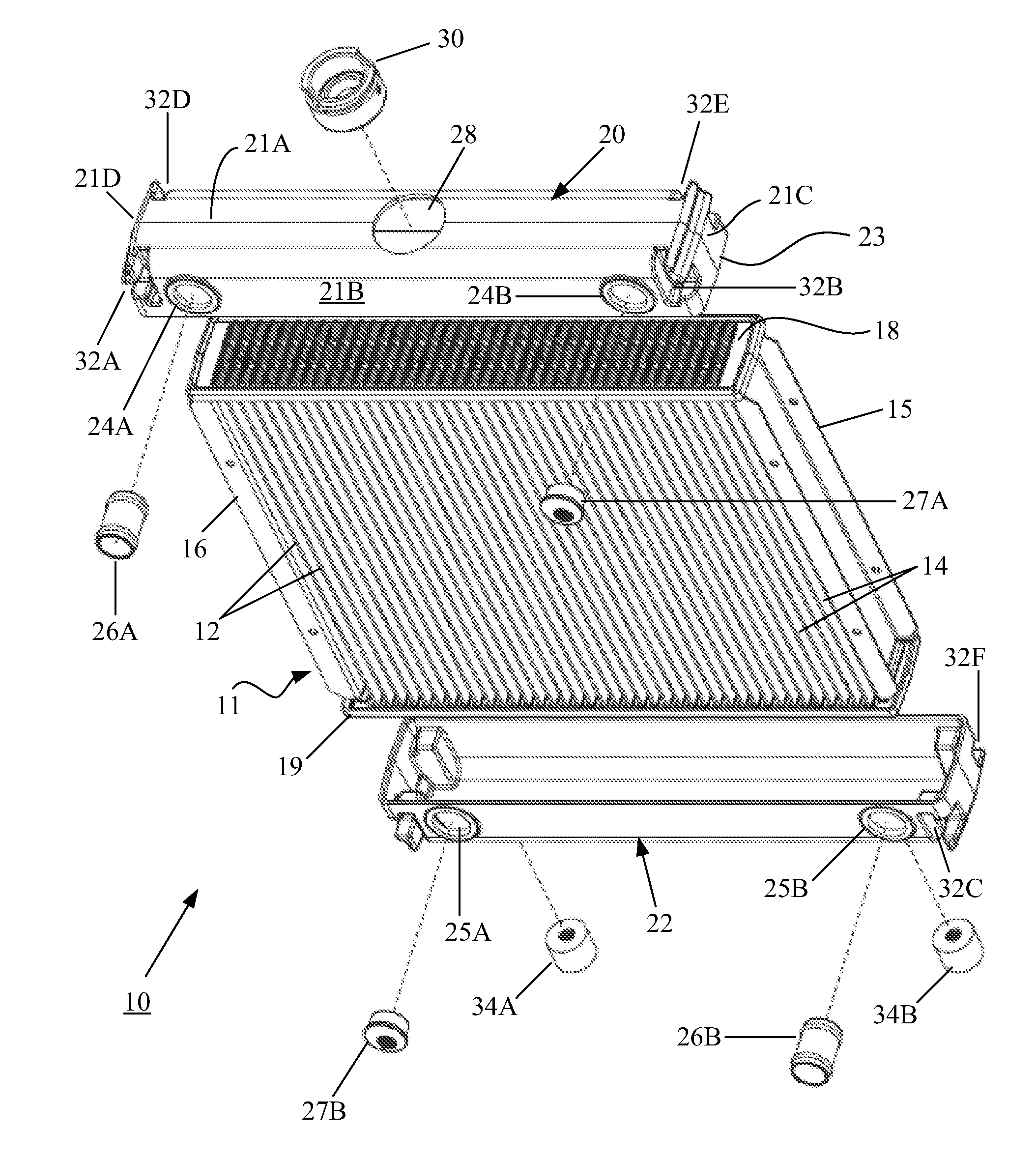
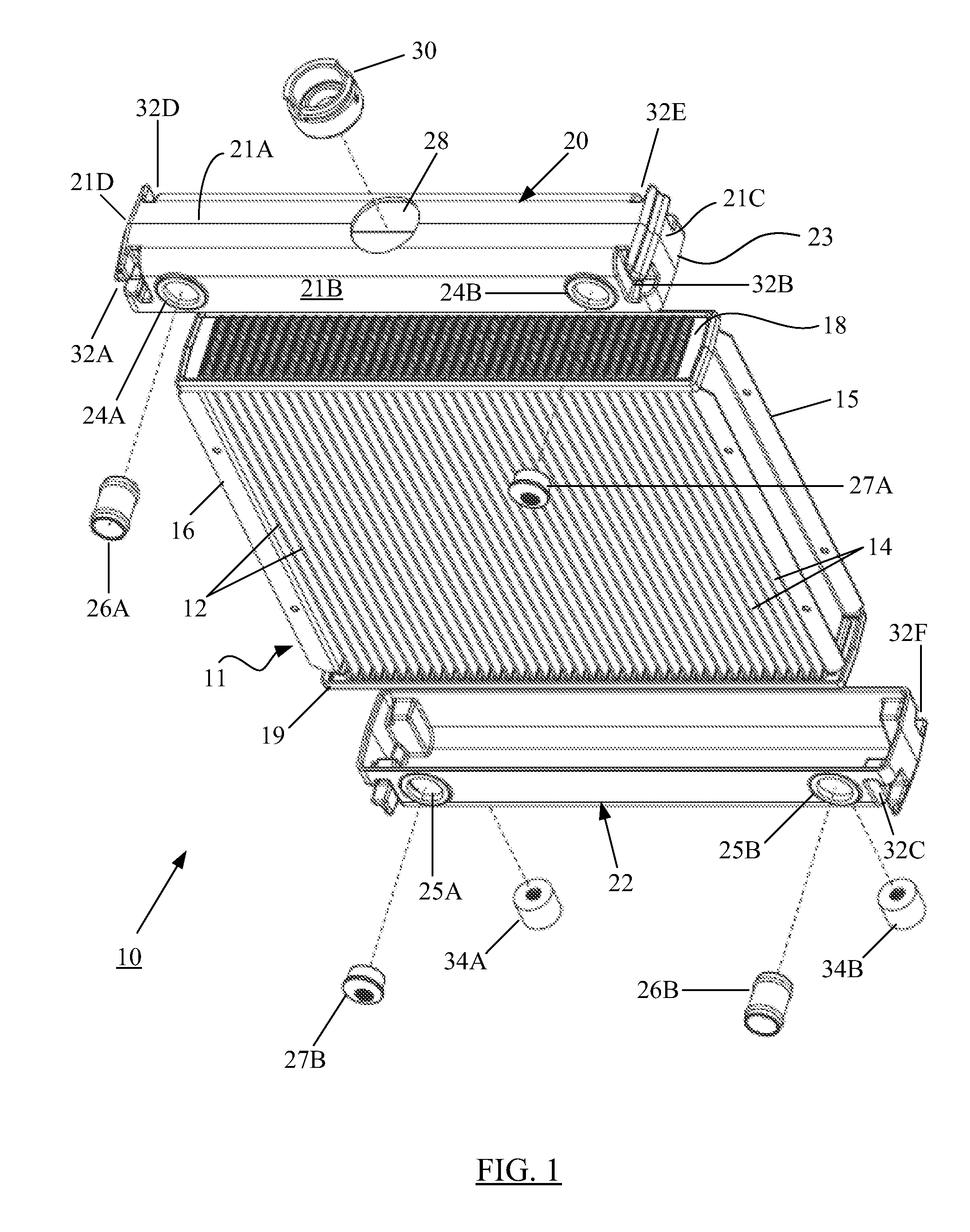
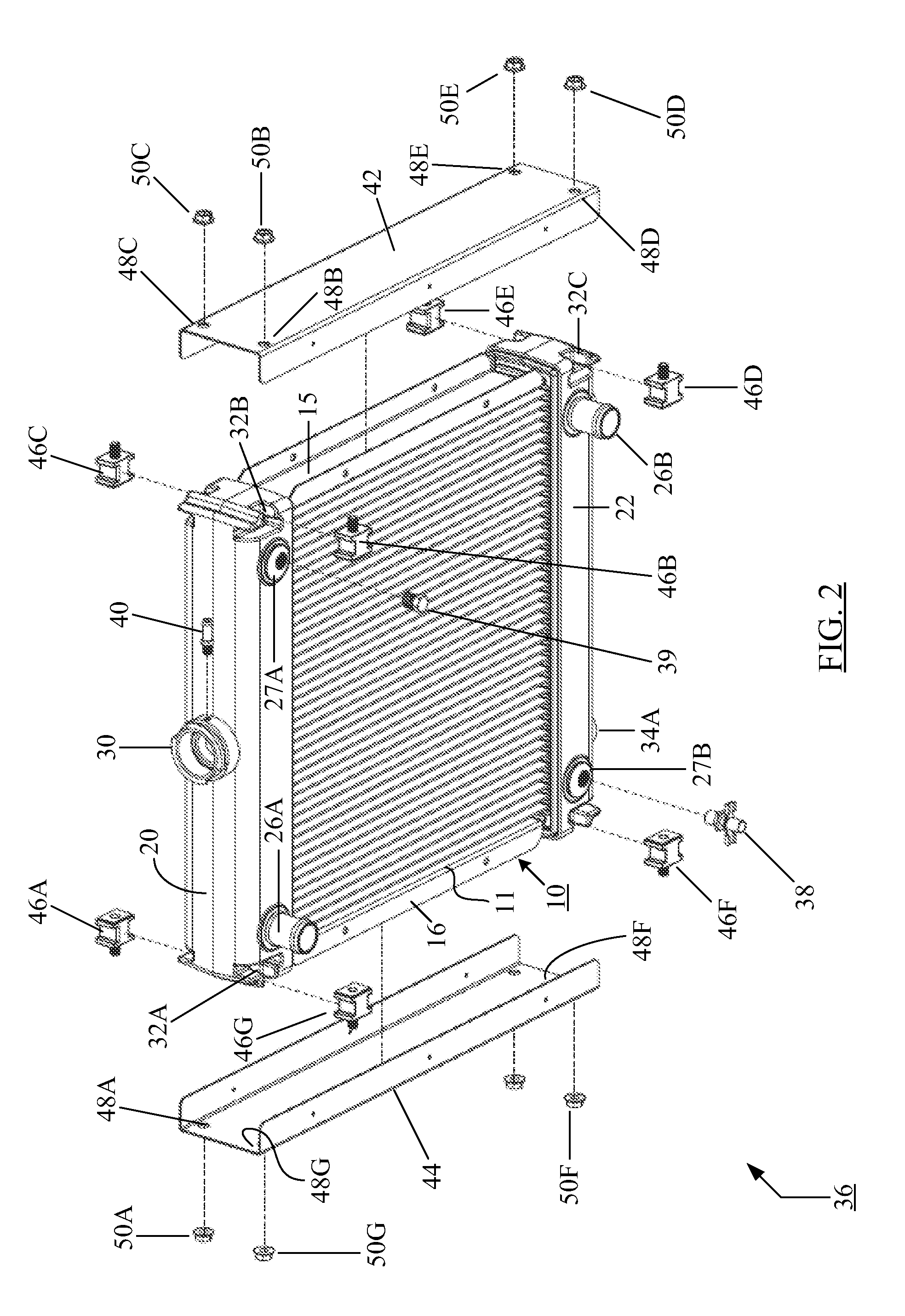
[0044]The accompanying figures and the description that follows set forth the present disclosure in embodiments of the present disclosure. However, it is contemplated that persons generally familiar with mechanical designs, and more particularly with designs of industrial heat exchangers, will be able to apply the teachings of the present disclosure in other contexts (e.g., for automotive radiators) by modification of certain details. Accordingly, the figures and description are not to be taken as restrictive of the scope of the present disclosure, but are to be understood as broad and general teachings. In the discussion herein, when any numerical value is referenced, such value is understood to be a practically-feasible design approximation taking into account variances that may be introduced by such mechanical operations as machining, tooling, drilling, casting, etc.

[0045]It is observed at the outset that the directional terms such as “top,”“bottom,”“right,”“left,”“horizontal,”“v...


PUM

PropertyMeasurementUnit
heightaaaaaaaaaa
heightaaaaaaaaaa
lengthaaaaaaaaaa

Abstract

A heat exchanger (such as a radiator) that provides for a consistent tank-to-header joint location. The tank generally includes at least two indentations and at least one isolator having a base at least partially disposed in one of the indentations and a coupler extending from the base for coupling the tank to at least one other component of the heat exchanger.

Description

BACKGROUND[0001]1. Field of the Disclosure[0002]The present disclosure generally relates to the field of heat exchangers including aluminum heat exchangers used to cool internal combustion engines.[0003]2. Brief Description of Related Art[0004]Heat exchangers are used to transfer thermal energy from one medium to another. For example, in an internal combustion engine cooling application, heat is transferred from the internal combustion engine to the cooling fluid and the cooling fluid is itself cooled as its heat is transferred to the atmosphere when the coolant flows through a radiator. The coolant flow to and from the radiator may be pumped, and a fan may be provided in the proximity of the radiator to blow air through the radiator. In any event, the coolant flow and corresponding cooling process continues during operation of the internal combustion engine, thereby maintaining the operating temperature of the internal combustion engine within acceptable limits and preventing the e...

Claims


Application Information

Patent Timeline
Patent Type & Authority Applications(United States)
IPC IPC(8): F28F7/00B65D90/02
CPCF28D1/05383F28F1/128F28F9/001F28F9/007F28F9/0224F28F21/06F28F21/08F28F9/002F01P3/18B62D25/084
Inventor RICHARDSON, DAVIDMEIER, BRIAN
Owner RICHARDSON COOLING PACKAGES
Why Eureka
Try Eureka