
Transmission cable

a technology of transmission cable and stp cable, which is applied in the direction of cables, insulated conductors, conductors, etc., can solve the problems of deterioration of the balance of the pair of stp cables b>9/b>, increase of skew, and damage to the cable, so as to prevent the deterioration of the attenuation characteristics

Inactive Publication Date: 2011-11-17
THE FUJIKURA CABLE WORKS LTD
View PDF2 Cites 73 Cited by
  • Summary
  • Abstract
  • Description
  • Claims
  • Application Information

AI Technical Summary

Benefits of technology

[0020]According to the transmission cable according to (1) above, since the plurality of signal wire pairs and the power wire pair constituting the transmission cable are arranged in a balanced manner, a heavy load is not applied to a part of the interior of the transmission cable and damage to these signal wire pairs and power wire pair is prevented.
[0022]According to the transmission cable according to (2) above, since the cross-sectional shape of the twisted-pair signal wire is made close to a true circle by providing the pair of first inclusions, the plurality of signal wire pairs and the power wire pair can be arranged in a balanced manner and damage to these signal wires and power wires is more securely prevented.
[0024]According to the transmission cable according to (3) above, since the plurality of signal wire pairs and the power wire pair can be arranged in a balanced manner due to the arrangement of the second inclusion, damage to these signal wire pairs and power wire pair is more securely prevented.
[0026]According to the transmission cable according to (4) above, the outer diameter of the collection of the twisted-pair signal wires, the plurality of twin-axial cables, and the power wire pair bundled together can be reduced.
[0028]According to the transmission cable according to (5) above, since no inclusion is arranged at the center of the cable, the outer diameter of the transmission cable can be reduced.
[0031]According to a transmission cable of the present invention, it is possible to prevent a deterioration in attenuation characteristics due to the damage thereof and to provide a USB cable in conformity with the USB 3.0 standard.

Problems solved by technology

Therefore, there is concern that the cables may be damaged.
When an insulated wire of the pair of STP cables 9 is damaged, the balance in the pair of STP cables 9 deteriorates and thus skew increases.
Therefore, there is concern that attenuation characteristics may deteriorate.
In addition, regarding the UTP cable 2, the impedance is reduced in a portion in which an insulated wire is damaged, whereby there is also concern that impedance mismatching may occur.
In addition, since the positions of the cables are not stabilized, the cross-sectional shape of the overall transmission cable 11 does not become a true circle, and thus there is also concern that the appearance may become worse.

Method used


Image

  • Transmission cable
  • Transmission cable
  • Transmission cable

Examples


first embodiment

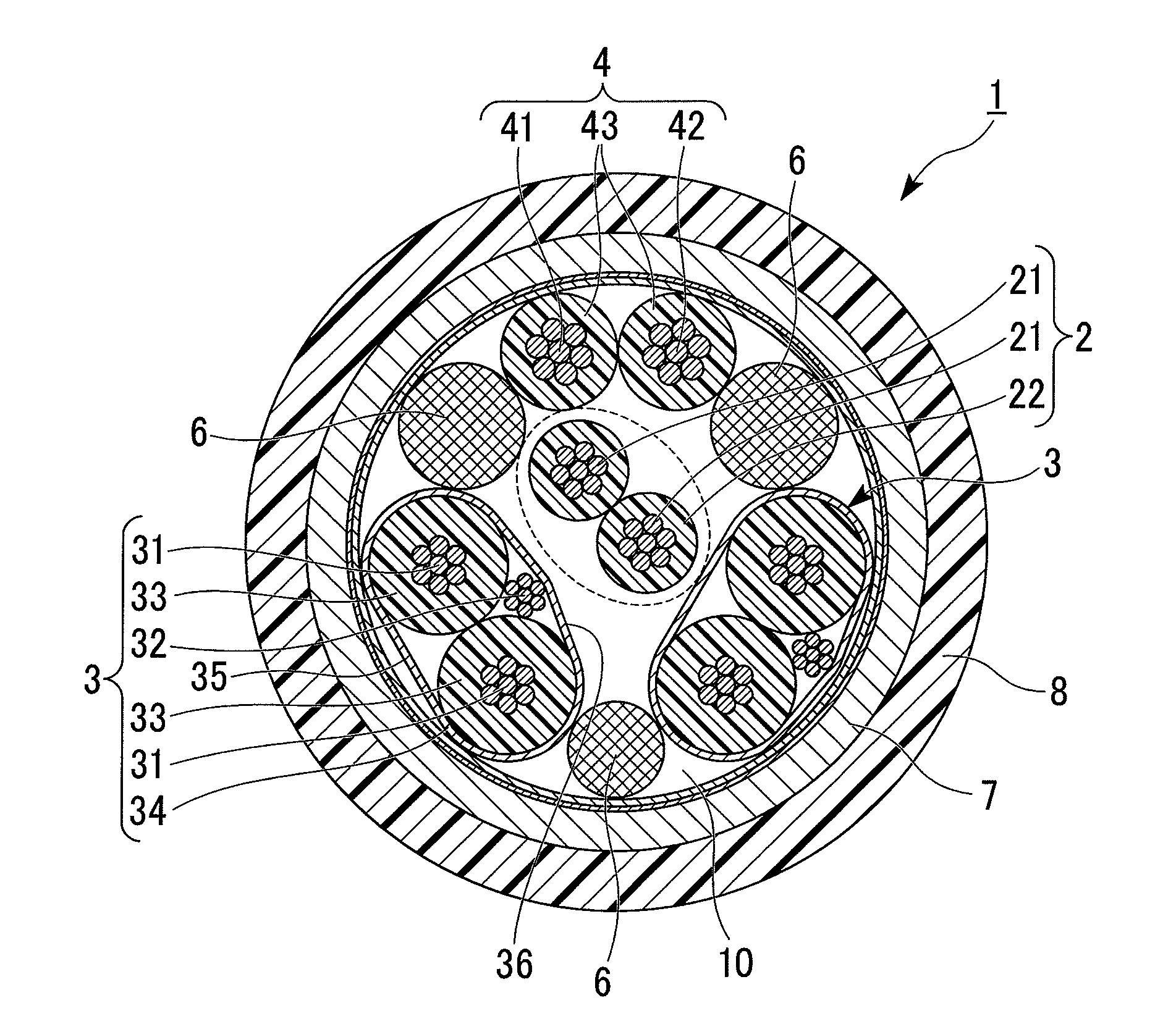
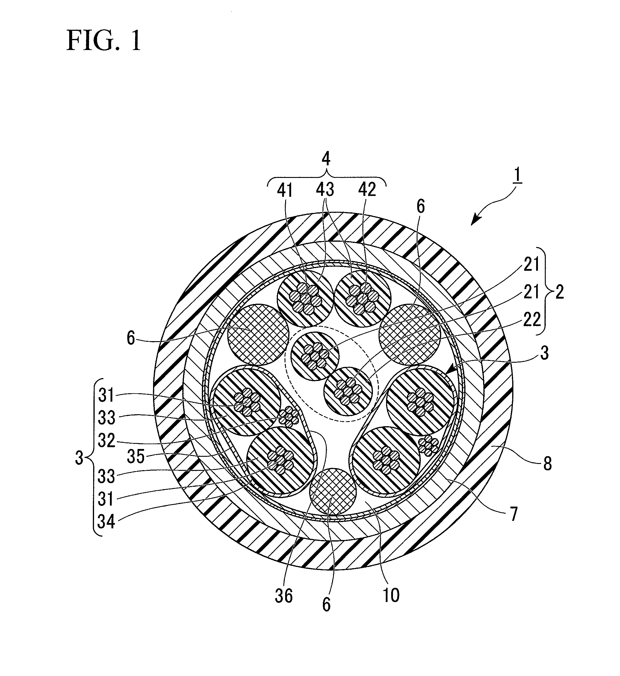
[0040]FIG. 1 is a cross-sectional view showing the configuration of a transmission cable 1 according to a first embodiment of the present invention. The transmission cable 1 is a cable in conformity with the USB 3.0 standard.

[0041]The transmission cable 1 has a configuration in which a shield material 7 is wound around a collective structure having a twisted-pair signal wire 2 with different outer diameters, two pairs of signal wire pairs 3, a power wire pair 4, and three second inclusions 6 which are arranged between the two pairs of signal wire pairs 3 and the power wire pair 4, and the outer circumference thereof is covered with an outer cover 8.

[0042]The twisted-pair signal wire 2 includes a pair of signal wires 21 and the signal wire pair 3 includes a pair of signal wires 31. Each signal wire 21 is covered with an insulating cover 22 and each signal wire 31 is covered with an insulating cover 33. Similarly, each of an electric power wire 41 and a ground wire 42 of the power wir...

second embodiment

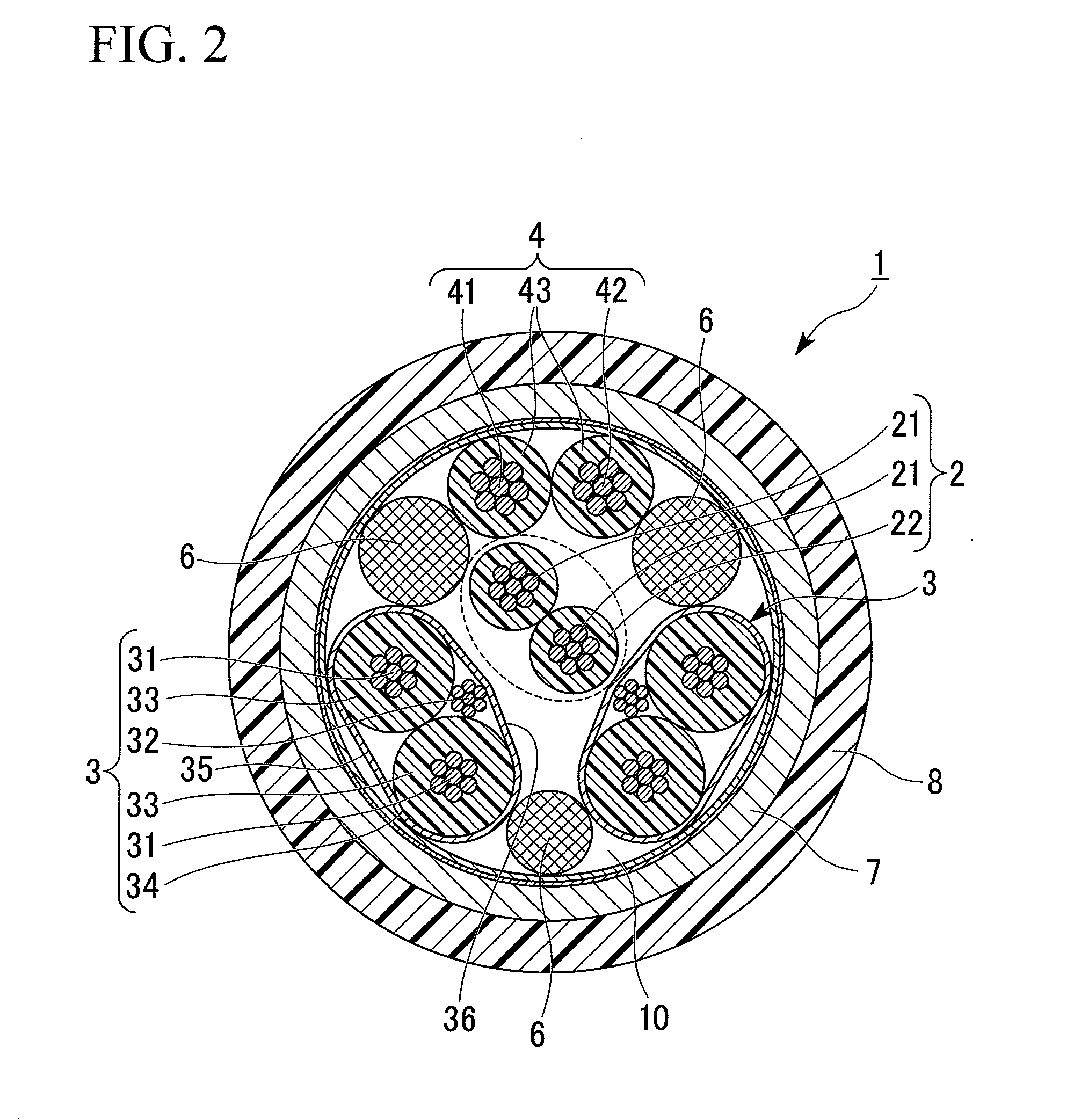
[0070]FIG. 4 is a cross-sectional view showing a transmission cable 1A according to a second embodiment of the present invention.

[0071]In the transmission cable 1A according to this embodiment, two first inclusions 23 are arranged along a twisted-pair signal wire 2 which is arranged at the center so as to sandwich the contact point of the twisted-pair signal wire 2 in between. Two signal wires 21 and two first inclusions 22 for a total of four are twisted together and quad-twisted.

[0072]The outer diameter of the first inclusion is 0.55 mm and the material for the first inclusion is polypropylene (PP).

[0073]The other configurations are the same as those in the above-described first embodiment. The twisted-pair signal wire 2 is arranged at approximately the center of a cross-section vertical to the longitudinal direction of the transmission cable 1, and signal wire pairs 3 and a power wire pair 4 are arranged therearound in a helical shape. The signal wire pair 3 is preferably a twin-...


PUM


Abstract

A transmission cable of the invention includes a twisted-pair signal wire; a plurality of signal wire pairs; and a power wire pair. The twisted-pair signal wire, the plurality of signal wire pairs, and the power wire pair are bundled together so that the twisted-pair signal wire is surrounded by the plurality of signal wire pairs and the power wire pair when viewed in cross-section vertical to a longitudinal direction thereof.

Description

CROSS-REFERENCE TO RELATED APPLICATION[0001]This is a Continuation Application of International Application No. PCT / JP2010 / 000844, filed on Feb. 10, 2010, which claims priority to Japanese Patent Application No. 2009-032925 filed on Feb. 16, 2009. The contents of the aforementioned applications are incorporated herein by reference.BACKGROUND OF THE INVENTION[0002]1. Field of the Invention[0003]The present invention relates to a transmission cable in conformity with the USB 3.0 standard, which is a standard for a next-generation universal serial bus (hereinafter, referred to as USB).[0004]2. Description of the Related Art[0005]USB is one of the data transmission path standards for connecting between an electronic device, such as a personal computer, and a peripheral device, and makes connection between devices easier. Currently, the USB 3.0 standard, which realizes a higher communication speed than that of the widely used USB 2.0 standard, is set as a next-generation standard.[0006]A...

Claims


Application Information

Patent Timeline
IPC IPC(8): H01B11/02
CPCH01B7/1895H01B11/12H01B9/003
Inventor UEDA, SHOUOGASAWARA, TAKASHI
Owner THE FUJIKURA CABLE WORKS LTD
Learn More