System for supplying energy

Inactive Publication Date: 2011-11-17
FORSELL PETER
View PDF5 Cites 140 Cited by
  • Summary
  • Abstract
  • Description
  • Claims
  • Application Information

AI Technical Summary

Problems solved by technology

However, such a switch is difficult to use because this removal of the implanted secondary coil from the load circuit by the switch results in the primary circuit seeing a low impedance in the pri

Method used


Image

  • System for supplying energy
  • System for supplying energy
  • System for supplying energy

Examples


Embodiment Construction

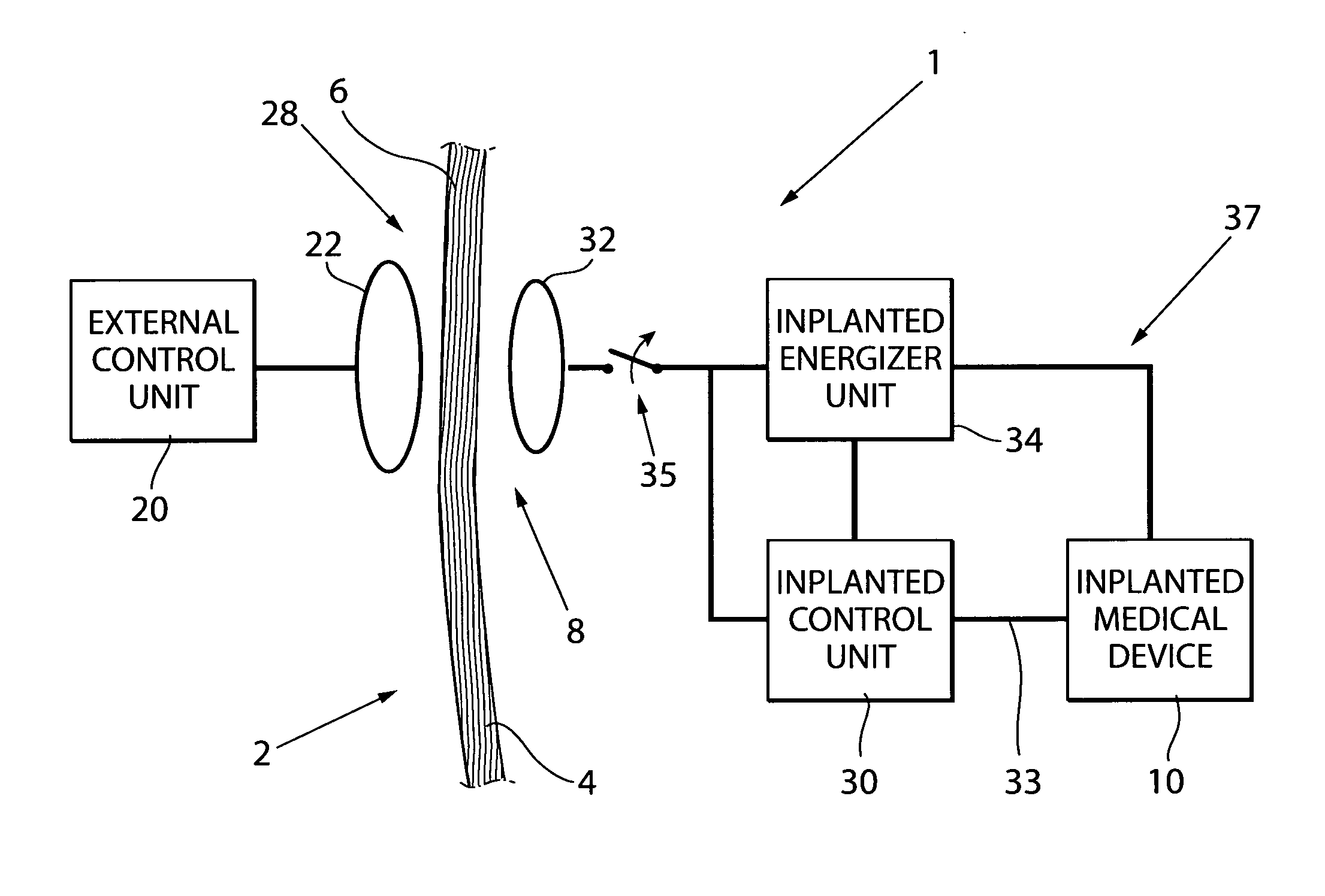
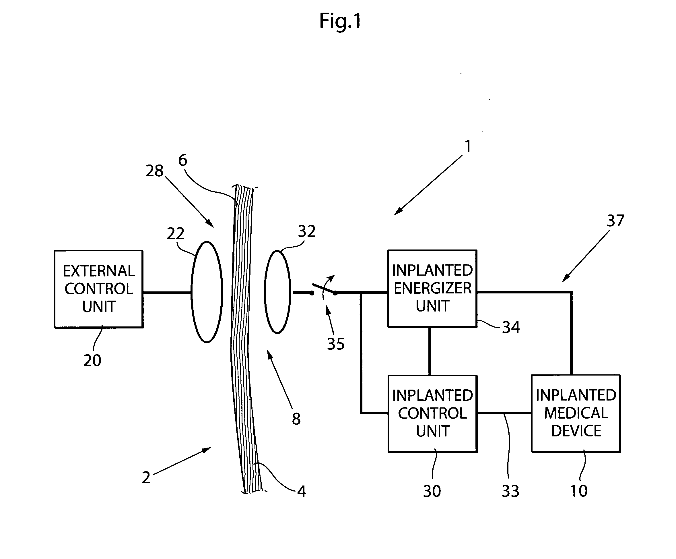
[0202]FIG. 1 is a schematic diagram of a system 1 using the coil arrangement of the present invention to supply energy or control signals to, or information from, a medical device 10 implanted in a human or animal patient's body. FIG. 1 shows the basic parts of the system 1. All parts placed to the left of the patient's skin 4 are located outside of the patient's body and all parts placed to the right of the skin 4 are implanted in the patient's body.

[0203]The system 1 includes an external control unit 20 located outside of the patient's body. The external control unit 20 functions as an external energizer that produces wireless energy to be transmitted to the implanted medical device. Thus, the external control unit 20 includes a generator for generating an alternating electromagnetic signal and a power amplifier. The external control unit 20 may also include a microprocessor and a modulator circuit for generating control signals to be sent to the implanted medical device 10. The m...


PUM


Abstract

A coil arrangement supplies energy or control signals to, or provides information from, a medical device implanted in a human or animal patient. The coil arrangement includes an external coil that is larger than an implanted coil so as to reduce the risk of damage to circuitry in an energy transmitter attached to the external coil that results from a low impedance at the external coil when a switch in an over-voltage protection circuit is opened to protect circuitry in a medical device attached to the implanted coil from being damaged by a too high voltage induced across the implanted coil.

Description

[0001]The present invention relates to medical implants, and, more particularly, to an improved coil arrangement for supplying energy to a medical device implanted in a human or animal patient's body in which an external coil in the arrangement is larger than an implanted coil in the arrangement so as to avoid damage to the medical implant's circuitry where the implanted coil is switched out of the medical implant's circuit to protect it from being damaged by a high voltage across the implanted coil.BACKGROUND OF THE INVENTION[0002]Medical devices are implanted in humans or animals for many reasons. Some of these devices are used to monitor one or more bodily functions. Other devices are used to stimulate, or out rightly control, bodily functions. Often, the medical devices will include some kind of communications circuit for receiving signals used to power and / or control the devices or the bodily functions monitored or controlled by the device.[0003]Medical devices are often intend...

Claims


Application Information

Patent Timeline
IPC IPC(8): H02J17/00
CPCA61N1/08A61N1/37229H02J7/025H02J5/005A61N1/3787H02J7/00034H02J50/80H02J50/90H02J50/10H02J2310/23
Inventor FORSELL, PETER
Owner FORSELL PETER
Why Eureka
Try Eureka