
Apparatus and method for assisting vertical takeoff vehicles

a technology of apparatus and vehicles, applied in the field of radar altimeters, can solve the problems of many incidents and accidents involving the use of vertical takeoff vehicles, vehicle damage or at worst destruction, and vehicle down, and achieve the effect of improving range resolution

Active Publication Date: 2011-11-17
E2V TECH (UK) LTD +1
View PDF15 Cites 48 Cited by
  • Summary
  • Abstract
  • Description
  • Claims
  • Application Information

AI Technical Summary

Benefits of technology

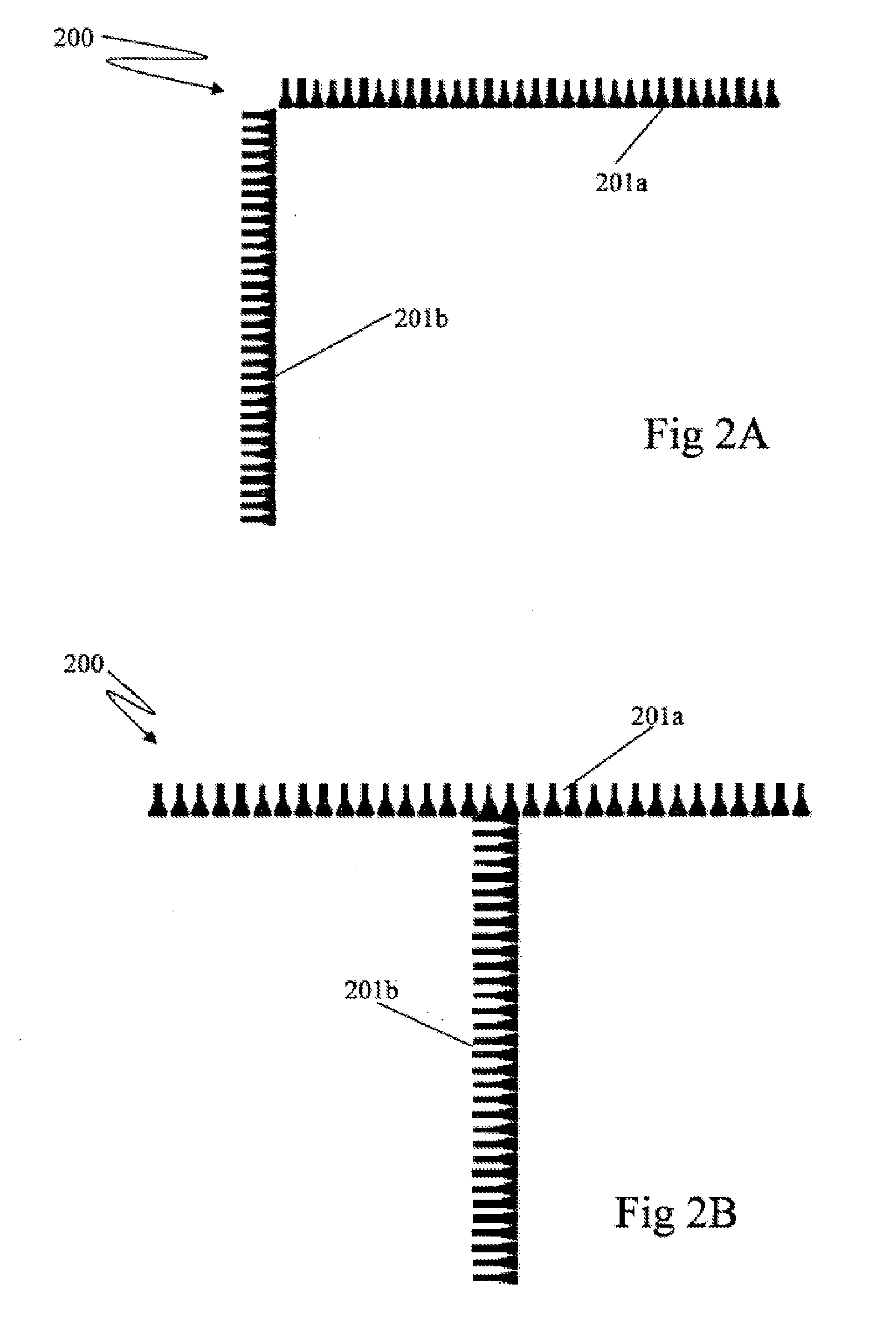
[0019]Preferably the transmitter and receiver elements have patterns covering 60 degrees in along track and cross track. The transmitter and receiver element patterns may be tilted forward to cover from +90 degrees forward-horizontal to 30 degrees behind nadir. Suitably the transmitter and receiver elements have the same polarisation. The transmitter and receiver elements may be formed into transmitter and receiver sub-arrays arranged orthogonal to one another. Suitably the spacing between the elements is about half a wavelength. Each element within the sub-arrays may be connected in series to reduce the number of active devices. Preferably the transmitter and receiver sub-arrays are arranged to form planar array wherein the transmitter and receiver elements are positioned adjacent to the array perimeter. The planar array may define any suitable closed planar shape such as a circle, square, rectangle, octagon or the like.
[0022]Where a frequency division multiplexing scheme is utilised to transmit the coded signals, a constant frequency separation is employed between the carrier frequencies of each pulses (i.e. the spacing between the carrier frequencies of each pulse in the frequency domain is identical). Preferably a variety of pulse compression techniques such as step-frequency range compression can be employed to further improve range resolution.

Problems solved by technology

Many incidents and accidents involving the use of vertical takeoff vehicles occur frequently during takeoff and landing operations.
Numerous accidents causing anywhere form minor damaged or at worst destruction of the vehicle have resulted from environmental factors such as terrain type, wing and rotor clearance etc.
One cause of accidents in landing operations is setting the vehicle down on steep or uneven terrain.
From the air it can be difficult to sight imperfections in the landing area.
Setting the craft down on steep or uneven surfaces can cause the craft to pitch and tip over.
In essence the debris that is kicked up into the air creates a cloud which can completely obscure the operators view to the landing zone and surrounding landmarks.
In the case of vehicles such as a helicopter, the increased turbulence created by the rotors (rotor wash) can create eddy currents within the particulate cloud.
A pilot not using the flight instruments for reference may instinctively try to level the aircraft, resulting in an accident.
Although the majority of the incidents occur during landing, there have been a significant number of incidents occurring during takeoff.
On average the number of brownout incidents occasioning damage costs the US military US$100 million per year.
In addition to the brownout problem a large number of helicopter operations are carried out under the cover of darkness.
During such operations pilots become more dependent upon their instruments and limited information regarding terrain from night vision systems (if available).
Neither of the altimeter Hager patents is capable of providing the pilot of any useful information regarding the tomography of the desired landing surface.
While the system of Judge is capable of assisting a pilot with identifying the position of the aircraft relative to the select landing zone and any obstacles within range of the aircraft, it does not provide the pilot of any useful information regarding the topography of the desired landing surface.

Method used


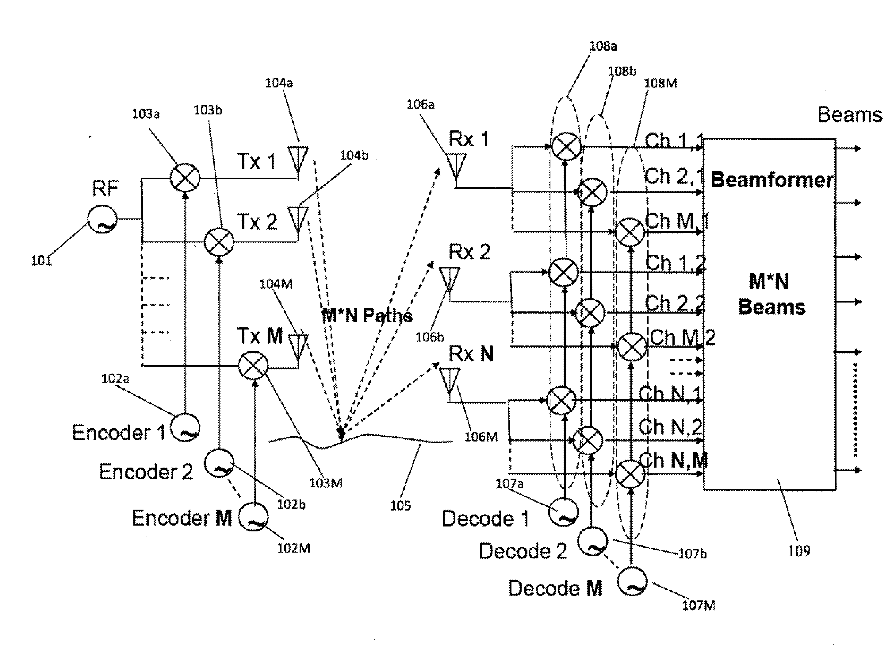
Image

  • Apparatus and method for assisting vertical takeoff vehicles
  • Apparatus and method for assisting vertical takeoff vehicles
  • Apparatus and method for assisting vertical takeoff vehicles

Examples


Embodiment Construction

[0032]In order to produce a finely detail ground profile image via radar a multiplicity of beams is required. This conventionally requires a scanning dish antenna or phased array radar with many antenna elements and associated scanning electronics, making such systems complex and expensive.

[0033]An alternative approach to the formation of multiple beams is to utilise Multiple Input Multiple Output (MIMO) technique in association with orthogonal or near orthogonal transmitter and receiver antenna arrays. The MIMO technique makes use of the fact that the signal received from the far field with a bi-static transmitter receiver pair is identical to the signal which would be received by a single mono-static transmit / receive element placed at the mid point between the bi-static pair. For convenience, where the targets are in the far field, the image computation can be based on the geometry arising from a notional plurality of transient elements. The technique can also be used for signals ...


PUM


Abstract

According to one aspect of the present invention, there is provided a radar altimeter which utilizes a downward looking MIMO phased array to form multiple beams, covering a relatively wide sector, e.g., + / −60 degrees or thereabouts. The distance to the ground is then measured in each beam allowing the ground profile to be formed. The beams may be tilted forward to cover from about +90 degrees forward (horizontal) to about 30 degrees behind nadir. The provision of such a forward tilt gives a greater degree of coverage in the direction of approach vector to the ground. This additional cover enables the altimeter to more accurately detect other vehicles in the proximity to the current approach vector of the vehicle to the desired landing zone.

Description

CROSS REFERENCE TO PRIOR APPLICATIONS[0001]This application is a continuation of International Application PCT / AU2010 / 000082, published as WO 2010 / 085846, with an international filing date of Jan. 28, 2010, which claims priority from Australian Patent Application No. 2009 / 900337, filed Jan. 30, 2009, all of which are hereby incorporated herein by reference for all purposes as if fully set forth herein.BACKGROUND OF THE INVENTION[0002]1. Field of the Invention[0003]The present application relates to apparatus and methods for assisting operators of vertical takeoff vehicles in landing operations within environments of low visual acuity. In particular although not exclusively the present application relates to a radar altimeter for assisting in landing operations of vertical takeoff vehicles.[0004]2. Discussion of the Background Art[0005]Many incidents and accidents involving the use of vertical takeoff vehicles occur frequently during takeoff and landing operations. Given the complex ...

Claims


Application Information

Patent Timeline
IPC IPC(8): H04N7/18
CPCG01S13/882G05D1/0676G01S2013/0254G01S13/913G05D1/0858G01S13/347
Inventor LONGSTAFF, DENNIS
Owner E2V TECH (UK) LTD
Learn More