Illumination structure and lamp tube structure for generating specific directional light sources

a technology of directional light source and lamp tube, which is applied in the direction of point-like light source, semiconductor device of light source, lighting and heating apparatus, etc., can solve the problems of high power consumption, high heat generation, and quick attenuation

Inactive Publication Date: 2011-11-17
LEDTECH ELECTRONICS CORP
View PDF4 Cites 73 Cited by
  • Summary
  • Abstract
  • Description
  • Claims
  • Application Information

AI Technical Summary

Benefits of technology

[0006]One particular aspect of the instant disclosure is to provide an illumination structure for generating specific direction

Problems solved by technology

However, compared to the newly developed light-emitting-diode (LED) lamps, these traditional lamps have the disadvantages of quick attenuation, high power consumption, high heat generation, short working life, high fragility, and being not recyclable.
However, like all the conventional lighting devices mentioned above, the halogen like also suffer from high operating temperature and low energy efficiency.
However, conventional LED designs often fall short in providing the uniform light projection capabi

Method used


Image

  • Illumination structure and lamp tube structure for generating specific directional light sources
  • Illumination structure and lamp tube structure for generating specific directional light sources
  • Illumination structure and lamp tube structure for generating specific directional light sources

Examples


Embodiment Construction

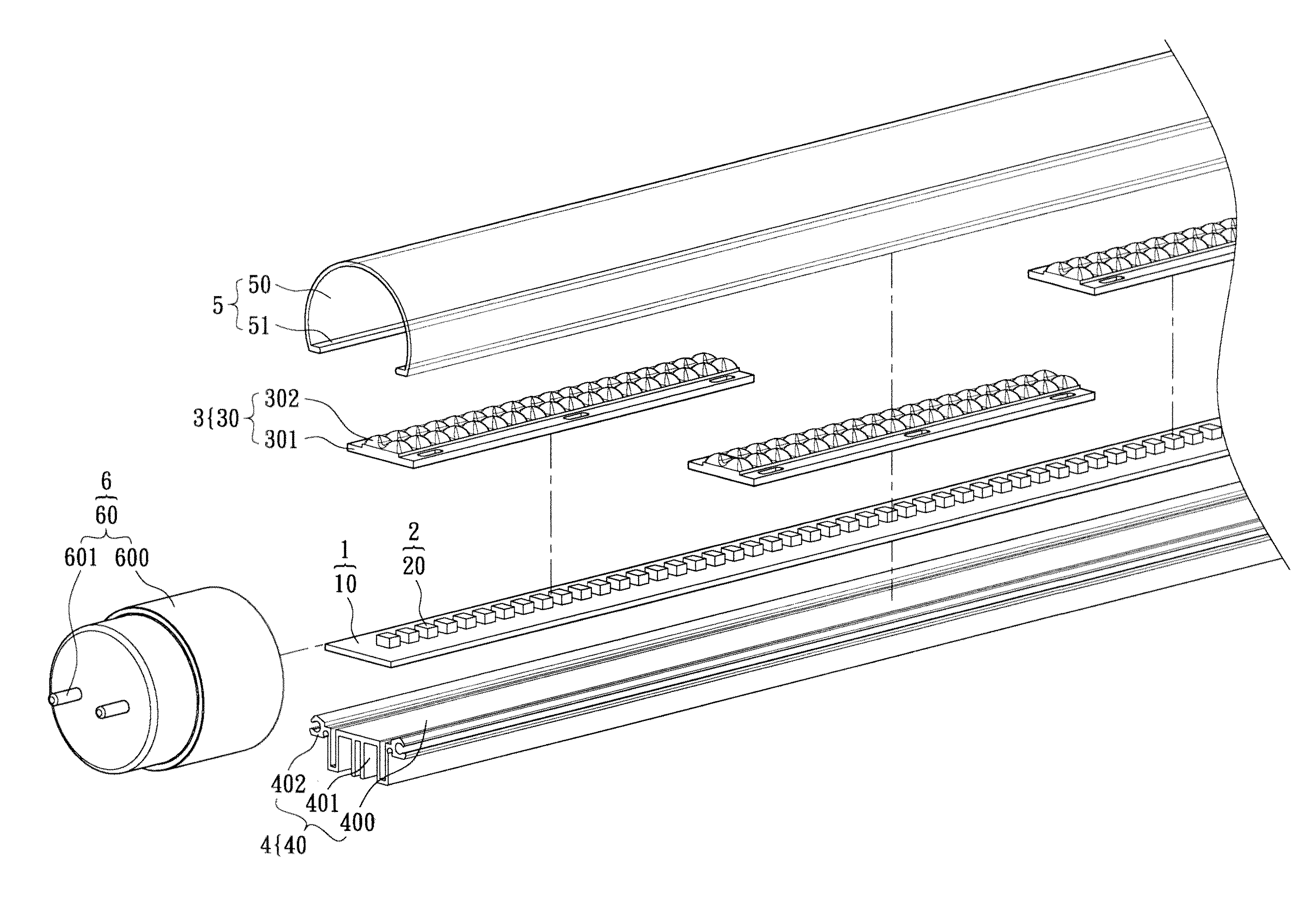
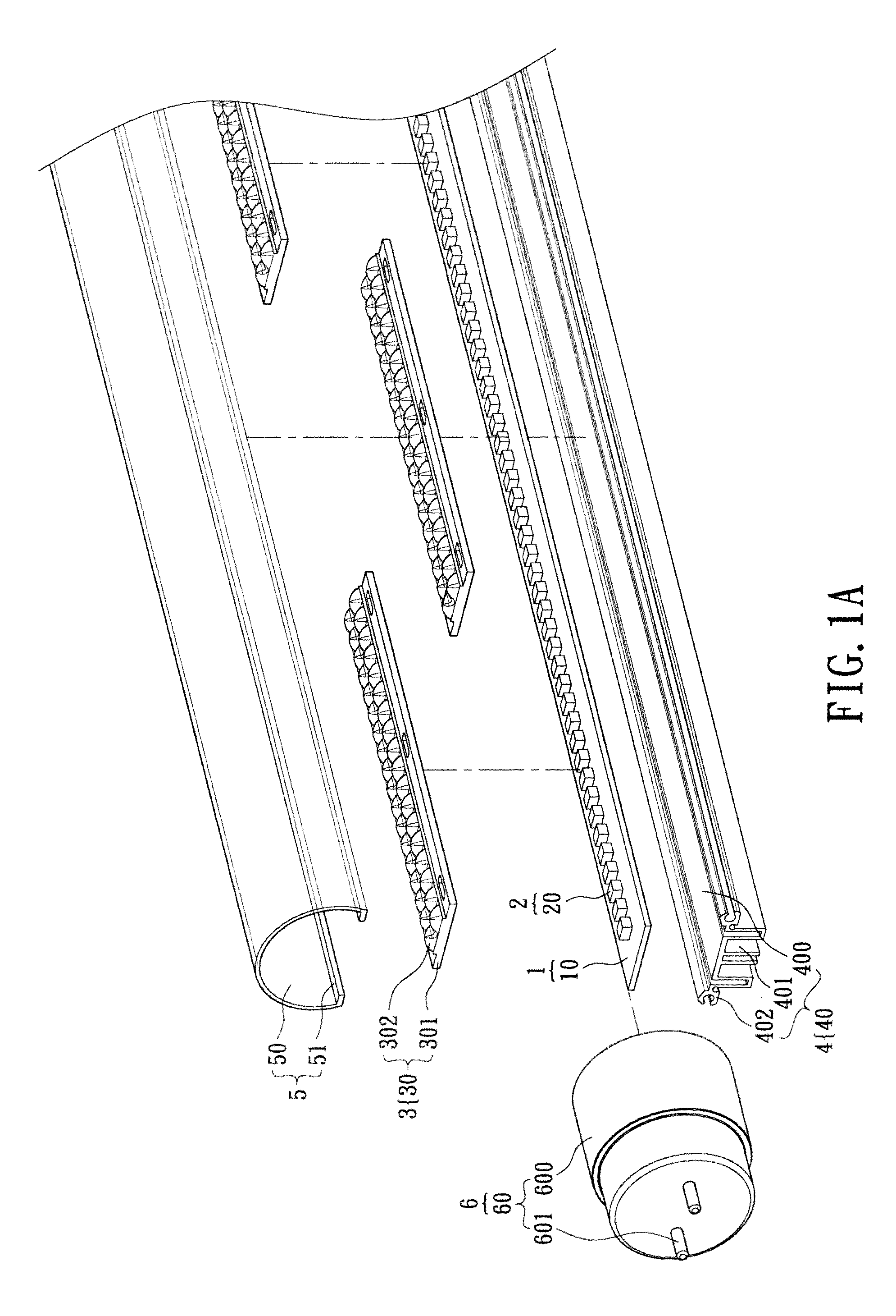
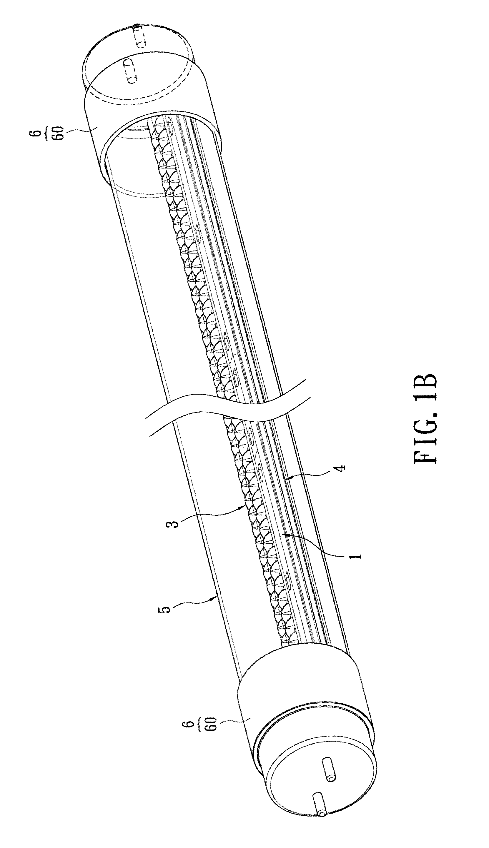
[0022]Referring to FIGS. 1A to 1C, the first embodiment of the instant disclosure provides a lamp tube structure for generating specific directional light sources, including: a substrate unit 1, a light-emitting unit 2, a lens unit 3, a heat-dissipating unit 4, a lamp shell unit 5 and a lateral cover unit 6.

[0023]The substrate unit 1 has at least one substrate body 10. For example, the substrate body 10 may be a circuit substrate having circuits formed thereon or an aluminum substrate having circuits formed thereon.

[0024]The light-emitting unit 2 has a plurality of light-emitting elements 20 disposed on and electrically connected to the substrate body 10. For example, each light-emitting element 20 may be an LED element that has been packaged by package resin (not shown) and can be electrically connected to the substrate body 10 by surface-mount technology, or each light-emitting element 20 may be an LED chip electrically contacting the substrate body 10 by COB (Chip On Board) techn...


PUM


Abstract

An illumination structure for generating specific directional light sources includes a substrate unit, a light-emitting unit and a lens unit. The substrate unit has at least one substrate body. The light-emitting unit has a plurality of light-emitting elements disposed on and electrically connected to the substrate body. The lens unit has a plurality of lens modules sequentially abutted against each other and disposed on the substrate body. Each lens module has a lens frame disposed on the substrate body and a plurality of protruding lens elements separated from each other by a predetermined distance and integrally formed on the lens frame, the protruding lens elements respectively correspond to the light-emitting elements, and each protruding lens element has at least one concave portion formed on a top side thereof and above each light-emitting element and at least two protrusion portions respectively integrally connected to two opposite sides of the concave portion.

Description

BACKGROUND OF THE INVENTION[0001]1. Field of the Invention[0002]The instant disclosure relates to an illumination structure and a lamp tube structure, and more particularly, to an illumination structure and a lamp tube structure for generating specific directional light sources.[0003]2. Description of Related Art[0004]The invention of the lamp greatly changed the style of building construction and the living style of human beings. Traditional lighting devices such as lamps that adopt incandescent bulbs, fluorescent bulbs, or power-saving bulbs have been generally well-developed and used intensively indoor illumination. However, compared to the newly developed light-emitting-diode (LED) lamps, these traditional lamps have the disadvantages of quick attenuation, high power consumption, high heat generation, short working life, high fragility, and being not recyclable. Thus, various high-powered LED lamps are created to replace the traditional lighting devices. Among them, tubular LED ...

Claims


Application Information

Patent Timeline
IPC IPC(8): F21V29/00F21V5/00
CPCF21K9/17F21S4/008F21V5/007F21V17/104F21V29/763F21V31/005F21Y2101/02F21Y2103/003F21K9/50F21V29/004F21V3/02F21S4/28F21K9/27F21K9/60F21K9/69F21Y2103/10F21Y2115/10F21V5/10
Inventor CHEN, WEI-CHUNMENG, PEI-HUNGWANG, FANG-PO
Owner LEDTECH ELECTRONICS CORP
Why Eureka
Try Eureka