Combination microscopy

a microscopy and sample technology, applied in the field of combination microscopy, can solve the problems of reducing the resolution of high-resolution microscopy, and reducing the accuracy of the microscopy

Active Publication Date: 2011-11-24
CARL ZEISS MICROSCOPY GMBH
View PDF0 Cites 49 Cited by
  • Summary
  • Abstract
  • Description
  • Claims
  • Application Information

AI Technical Summary

Benefits of technology

[0015]The invention thus presents a combination, previously not yet realized or described in the state of the art, of particular high-resolution microscopy methods with standard microscopy methods. It is thereby possible to image comparatively small sample field sections (also called region of interest, or ROI) in high resolution and still supplement these with standard microscopy acquisitions or thus reveal them. Measurement cycles in high-resolution microscopy are also simplified by using data from the standard microscopy method, or increase the quality of the data which are obtained with their high-resolution microscopy methods.
[0040]The microscope according to the invention has a particularly simple structure if the individual partial illumination beam paths of the modules are combined cascade-like to a main illumination beam path which is then coupled in at the beam splitter for the detection beam path. The individual partial illumination beam paths are thus coupled into the total illumination beam path at different points, for example by the mentioned switching means. Switching means are of course not necessary when the activation or de-activation of the individual partial illumination beam paths can take place in another way, for example in the affected modules themselves.

Problems solved by technology

However, laser scanning microscopy allows a very much higher depth of field, although with both microscopes the optical resolution is diffraction-limited by physical laws.
The gain in resolution with high-resolution microscopy is at the cost of a lower measuring speed, a smaller measuring field, as well as limitations in respect of the penetration depth and the tagging substances that can be used for the luminescence microscopy.
This is particularly awkward if it is wished to examine smaller areas in a large sample or to track a temporal development of a sample which proceeds at varying speeds.

Method used


Image

  • Combination microscopy
  • Combination microscopy
  • Combination microscopy

Examples


Embodiment Construction

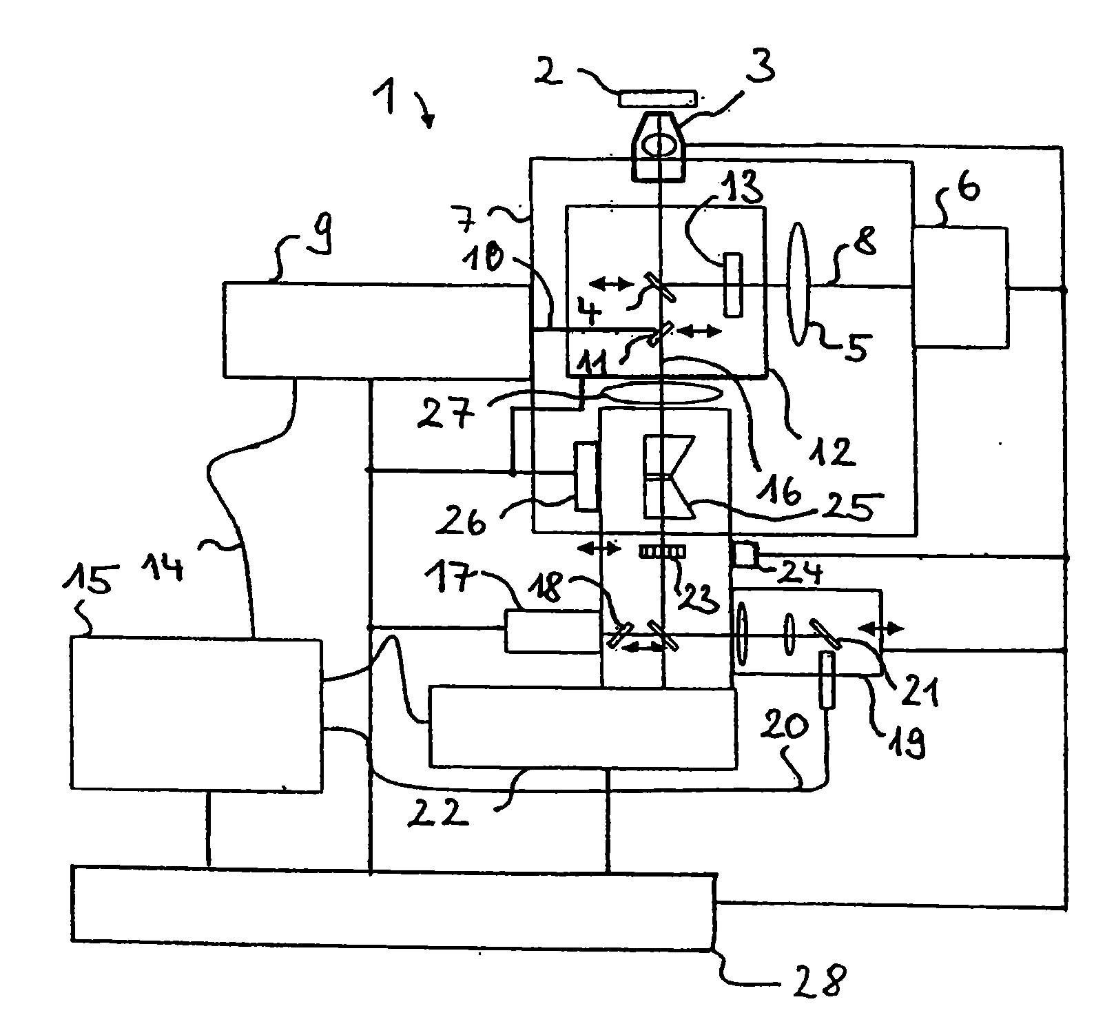
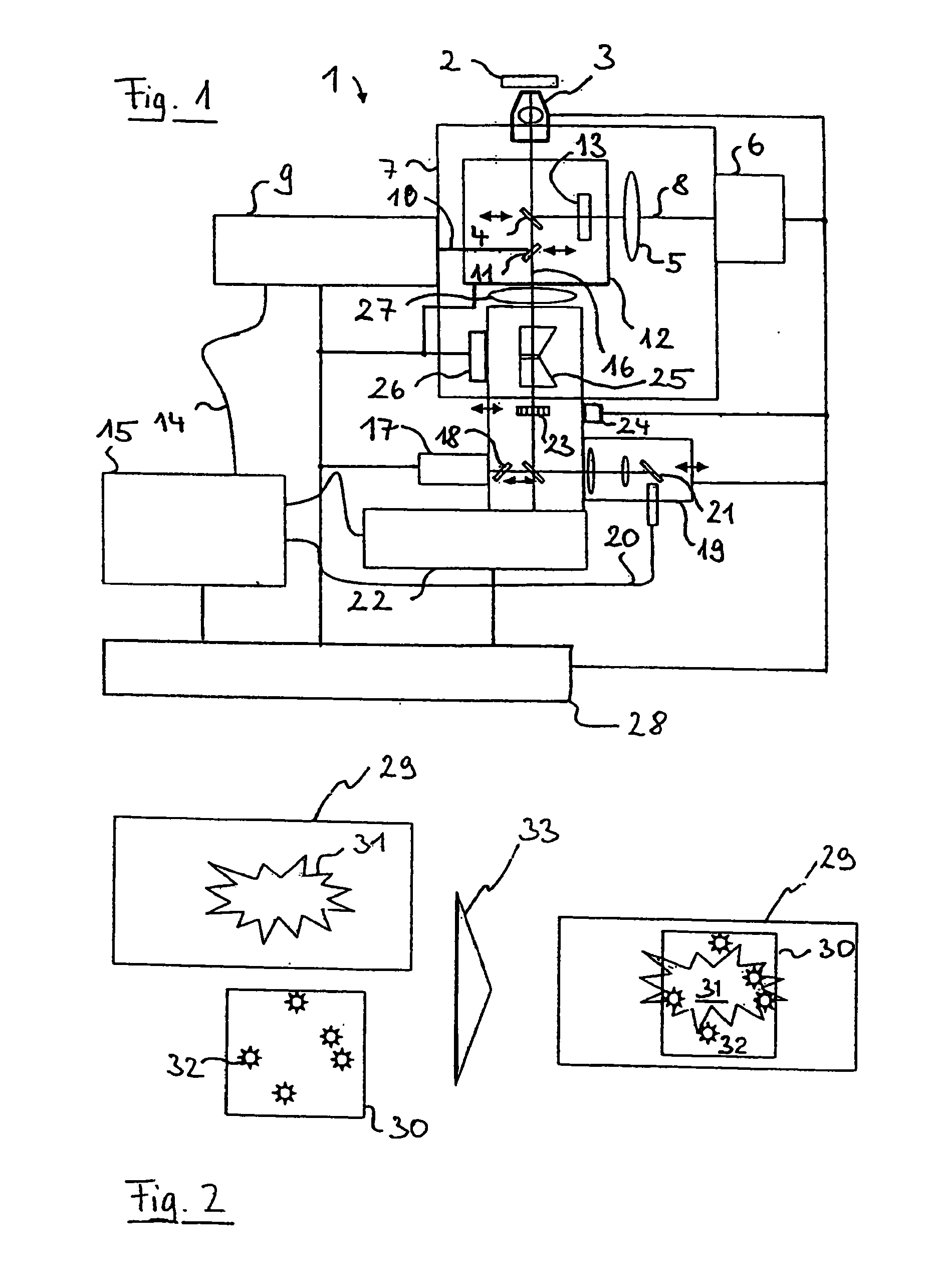
[0047]In FIG. 1, a microscope 1 is represented which can carry out standard microscopy methods, i.e. microscopy methods the resolution of which is diffraction-limited, simultaneously with high-resolution microscopy methods, i.e. with microscopy methods the resolution of which is increased beyond the diffraction limit. The microscope 1 is modular in structure, and it is described in a comprehensive expansion stage to better illustrate the invention. However, a reduced structure with few modules is also possible. The modular structure is also not necessary; a one-piece or non-modular design is likewise possible. The microscope 1 of this example of FIG. 1 is constructed on the basis of a conventional laser scanning microscope and senses a sample 2.

[0048]It has an objective 3 through which the radiation passes for all microscopy methods. Via a beam splitter 4, the objective 3 images the sample together with a tube lens 5 onto a CCD detector 6 which is an example of a generally possible ...


PUM


Abstract

A method for generating an image of a sample by a microscopy method including varying local resolution, wherein at least two of the following microscopy methods are combined: laser scanning microscopy, a microscopy method wherein the sample is excited to luminescence by structured line or wide area illumination, and a first microscopy image is generated from the images thus obtained, having increased local resolution greater than the optical resolution of the image, a further microscopy method according to the PAL principle, by which a second microscopy image is generated, indicating geometric locations of marker molecules emitting luminescent radiation at an increased local resolution relative to the optical resolution, and a further microscopy method, wherein the sample is marked using marking molecules suitable for the STED, ESA, or RESOLFT technique, and a third microscopy image is generated of STED, ESA, or RESOLFT, wherein the obtained images are superimposed.

Description

PRIORITY CLAIM[0001]The present application is a National Phase entry of PCT Application No. PCT / EP2009 / 007693, filed Oct. 28, 2009, which claims priority from German Application Number 102008054317.9, filed Nov. 3, 2008, the disclosures of which are hereby incorporated by reference herein in their entirety.FIELD OF THE INVENTION[0002]The invention relates to a method and a microscope for the microscopy of a sample, wherein several microscopy methods differing in their resolution are combined.BACKGROUND[0003]The examination of samples by means of microscopy is a broad technical field for which there are varied technical solutions. Starting from the standard light microscopy, widely different microscopy methods have evolved.[0004]A standard field of use of light microscopy for examining biological preparations is luminescence microscopy. In this process, particular dyes (so-called phosphors or fluorophores) are used for the specific tagging of samples, e.g. of cell parts. The sample ...

Claims


Application Information

Patent Timeline
Patent Type & Authority Applications(United States)
IPC IPC(8): G01J1/58
CPCG02B21/367G02B21/0076G02B27/642G02B27/58G01N21/6458
Inventor WOLLESCHENSKY, RALFKLEPPE, INGOKRAMPERT, GERHARDKEMPE, MICHAEL
Owner CARL ZEISS MICROSCOPY GMBH
Why Eureka
Try Eureka