Reactive power management

a technology of reactive power flow and reactive power, applied in the direction of reactive power adjustment/elimination/compensation, electric variable regulation, energy industry, etc., can solve the problems of phase shift in current flowing in the network with respect to voltage, burden on the power supplier, energy loss in the network, etc., to prevent oscillations and provide a hysteresis in provision

Active Publication Date: 2011-11-24
REACTIVE TECH FINLAND
View PDF9 Cites 25 Cited by
  • Summary
  • Abstract
  • Description
  • Claims
  • Application Information

AI Technical Summary

Benefits of technology

[0027]This provides a hysteresis in the provision of reactive power to the electricity distribution network, preventing oscillations occurring in the functioning of the device, and disrupting current flow in the electricity distribution network.
[0028]Preferably, the control means is arranged to change the reactive power in response to a predetermined time period elapsing after the detecting means detects the change in the reactive power characteristic. This also prevents oscillations from being introduced into the electricity flow in the system.

Problems solved by technology

Such devices produce a reactive current component which flows at ±90° to the voltage; this results in a phase shift in the current flowing in the network with respect to the voltage.
Further, energy losses in the network, due to e.g. heating of electric power lines, depend on the total current flow, irrespective of whether the current flow is real or reactive.
Accordingly, such phase differences effectively increase the size of the total current that must be generated and supplied by a power provider in order to meet the demands of its customers; this places an economic burden on the power supplier, increasing the cost of electrical power generation.
Similarly, the amount or resources consumed by the power provider in order to supply a given amount of power to a consumer is increased, which may have undesirable environmental consequences.
Further, network elements such as transformers and power lines are dimensioned according to total the size of the current (whether real or reactive) flowing in the network; their operation is therefore adversely effected by any reactive current flow (due to thermal losses and so on).
However, reactive power compensation is effective only at short distances (due to e.g. thermal losses), and, furthermore, the current-voltage phase difference may vary significantly from location to location within the electricity distribution network; this means that reactive power compensation at a small number of large scale power providers does not effectively compensate for localised current-voltage phase differences.
However, the system of US20090200994 requires central control and cannot react to more localised changes in local network voltage-current phase differences.

Method used


Image

  • Reactive power management
  • Reactive power management
  • Reactive power management

Examples


Embodiment Construction

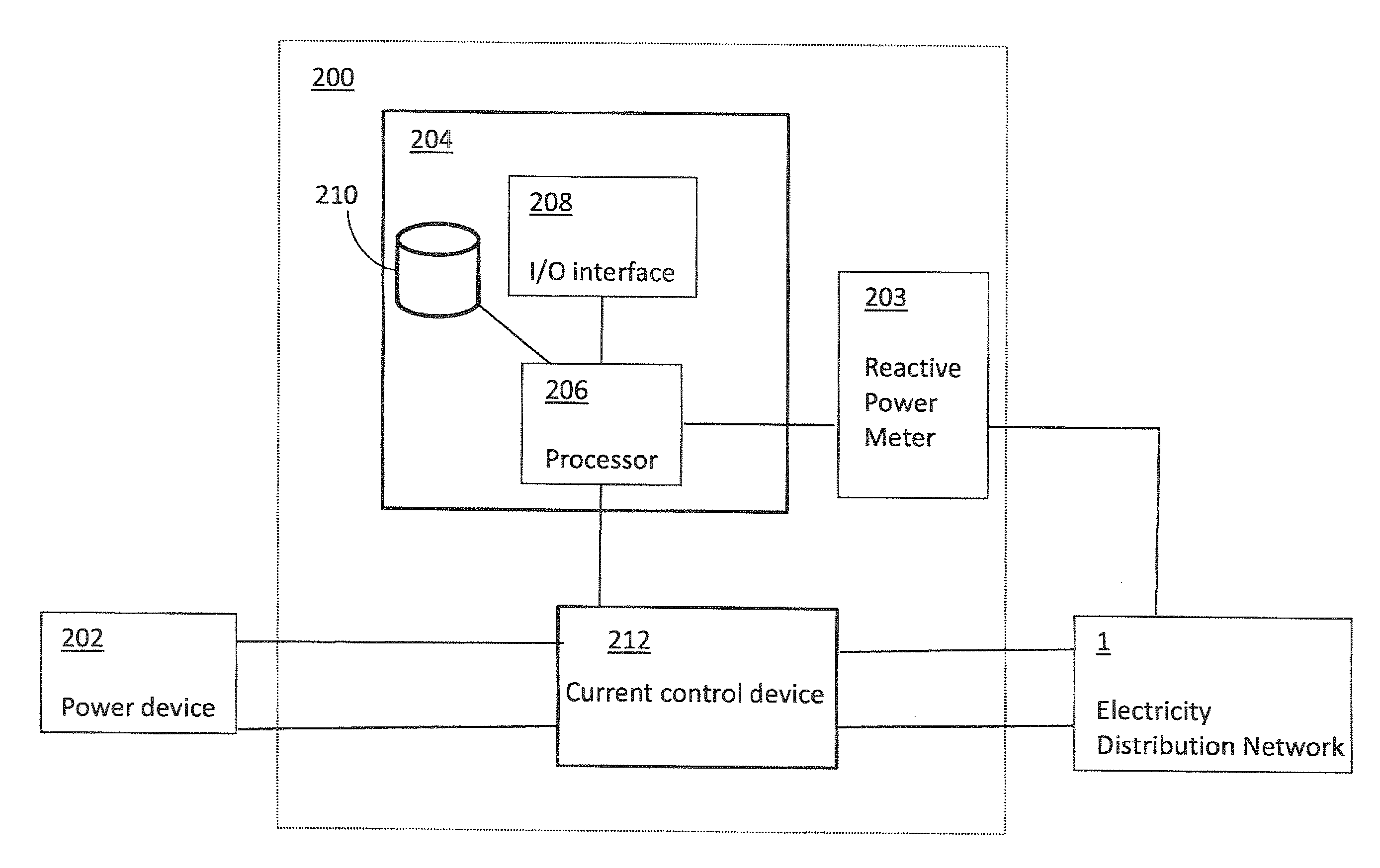
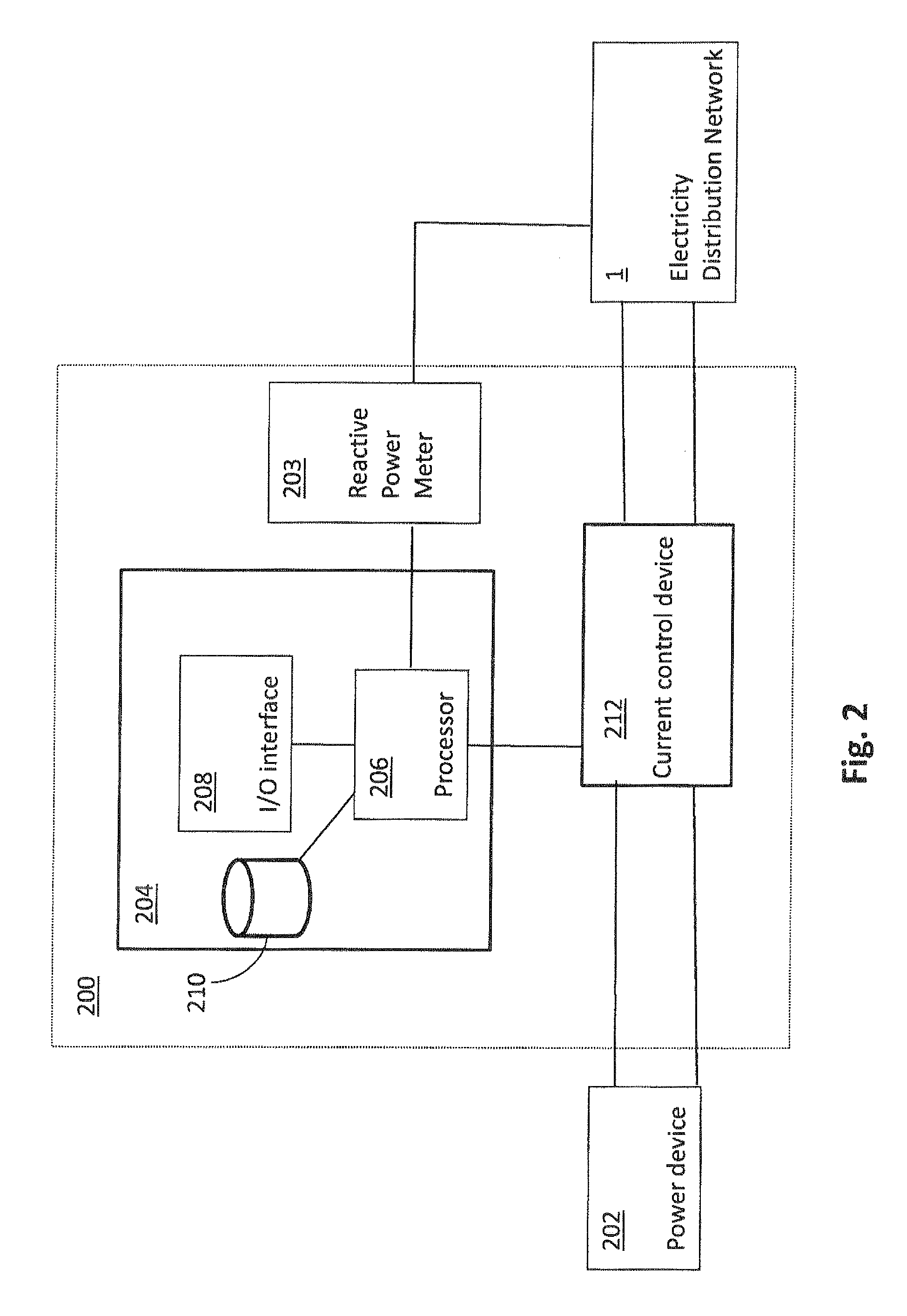
[0061]FIG. 2 shows a reactive power control device 200 for use in controlling a phase difference between the current and the voltage of electricity flowing in an electricity distribution network 1 at the location of a power device 202. The power device 202 may be a consumption device, for example, a low power consumption device, having a power rating of less than 500 W, such as an energy saving lamp, a mobile telephone charger, computing device supply, a medium sized power device, having a power rating of between 500 W and 10 kW, such as a personal electric vehicle (PEV), or a large power device, having a power rating of more than 10 kW, such as industrial machinery located at a factory. It should be noted that the devices may be single-phase or multi-phase; in the latter case the above power ratings apply per phase.

[0062]When the power device 202 comprises a power consumption device power is supplied to the power device 202 from the electricity distribution network 1, typically in ...


PUM


Abstract

Embodiments of the invention relate to devices and methods and systems for controlling a reactive power contribution to reactive power flowing in an electricity distribution network, so as to optimise this reactive power flow. Conventional methods of controlling reactive power flow focus on minimising a reactive power contribution by power provision and power consumption devices connected to the electricity distribution network, in accordance with, for example, regulations governing a maximum allowed power factor and/or under the control of a central controlling entity. However, such methods are slow to react to changing network conditions, and do not take account of local variations in reactive power. In an embodiment of the present invention, there is provided a reactive power control device for use with a power consumption and/or provision device. The reactive power control device comprises detecting means for detecting, at the power device, a reactive power characteristic of electrical power flowing in the electric power distribution network, the reactive power characteristic relating to a reactive power component of electricity flowing in the network. The reactive power control device further comprises control means for controlling, on the basis of the detected reactive power characteristic a reactive power contribution to the electricity distribution device so as to adjust a value of the detected reactive power characteristic. This enables individual power consumption and/or provision devices to react autonomously to local variations in the electricity distribution network, and to provide a reactive power contribution, to drive the detected reactive power characteristic towards a desired value.

Description

CROSS-REFERENCE TO RELATED APPLICATIONS[0001]The present application claims priority under 35 USC 119 of UK Patent Application GB 1008685.8 filed May 25, 2010 and UK Patent Application GB 1013987.1 filed Aug. 20, 2010, the entire disclosure of each of which is incorporated herein by reference.FIELD OF THE INVENTION[0002]The present invention relates to management of reactive power flow in an electricity distribution network. In particular, but not exclusively, it relates to devices and methods for controlling reactive power flow at power consumption and / or provision devices.BACKGROUND OF THE INVENTION[0003]Supply of electricity from providers such as power stations, to consumers, such as domestic households and businesses, typically takes place via an electricity distribution network. FIG. 1 shows an exemplary electricity distribution network 1 comprising an electricity transmission grid 100 and an electricity distribution grid 102. The transmission grid is connected to generating p...

Claims


Application Information

Patent Timeline
Patent Type & Authority Applications(United States)
IPC IPC(8): G05F1/70
CPCH02M1/4208H02J3/1892Y02P80/10G06F1/18H02J3/18
Inventor HUOMO, HEIKKI
Owner REACTIVE TECH FINLAND
Why Eureka
Try Eureka