Wire-grid polarizer and process for producing the same

a polarizer and wire-grid technology, applied in the direction of polarising elements, instruments, optical elements, etc., can solve the problems of low productivity of the wire-grid polarizer in item (1), low light use efficiency of the absorption polarizer, etc., and achieve low angle dependency, low wavelength dependency, and high degree of polarization

Inactive Publication Date: 2011-11-24
ASAHI GLASS CO LTD
View PDF13 Cites 9 Cited by
  • Summary
  • Abstract
  • Description
  • Claims
  • Application Information

AI Technical Summary

Benefits of technology

[0032]The wire-grid polarizer according to the present invention has not only a high degree of polarization, a high p-polarized light transmittance and a high s-polarized light reflectance but also a low angle dependency and a low wavelength dependency in terms of optical properties in the visible light region.
[0033]The process for producing a wire-grid polarizer according to the present invention is capable of producing a wire-grid polarizer, which has not only a high degree of polarization, a high p-polarized light transmittance and a high s-polarized light reflectance but also a low angle dependency and a low wavelength dependency in terms of optical properties in the visible light region.
[0034]In particular, according to the present invention, it is possible to obtain a wire-grid polarizer, which has a p-polarized light transmittance of at least 70%, an s-polarized light reflectance of at least 70% and a degree of polarization of at least 99.5%.BRIEF EXPLANATION OF THE DRAWINGS
[0035]FIG. 1 is a perspective view showing the wire-grid polarizer according to an embodiment of the present invention.
[0036]FIG. 2 is a perspective view showing the light-transmitting substrate according to the embodiment of the present invention.
[0037]FIG. 3 is a perspective view showing the wire-grid polarizer according to another embodiment of the present invention.

Problems solved by technology

Such an absorptive polarizer has a low light use efficiency because of absorbing one of polarized light waves.
Among them, the wire-grid polarizer in item (1) has a low productivity since the fine metallic wires are disposed by lithography.

Method used


Image

  • Wire-grid polarizer and process for producing the same
  • Wire-grid polarizer and process for producing the same
  • Wire-grid polarizer and process for producing the same

Examples


first embodiment

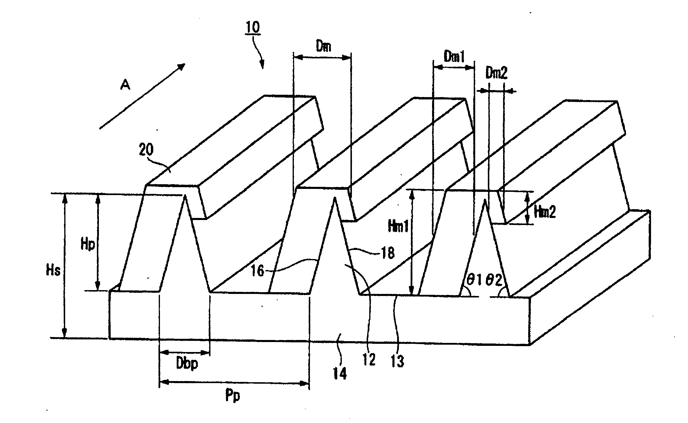
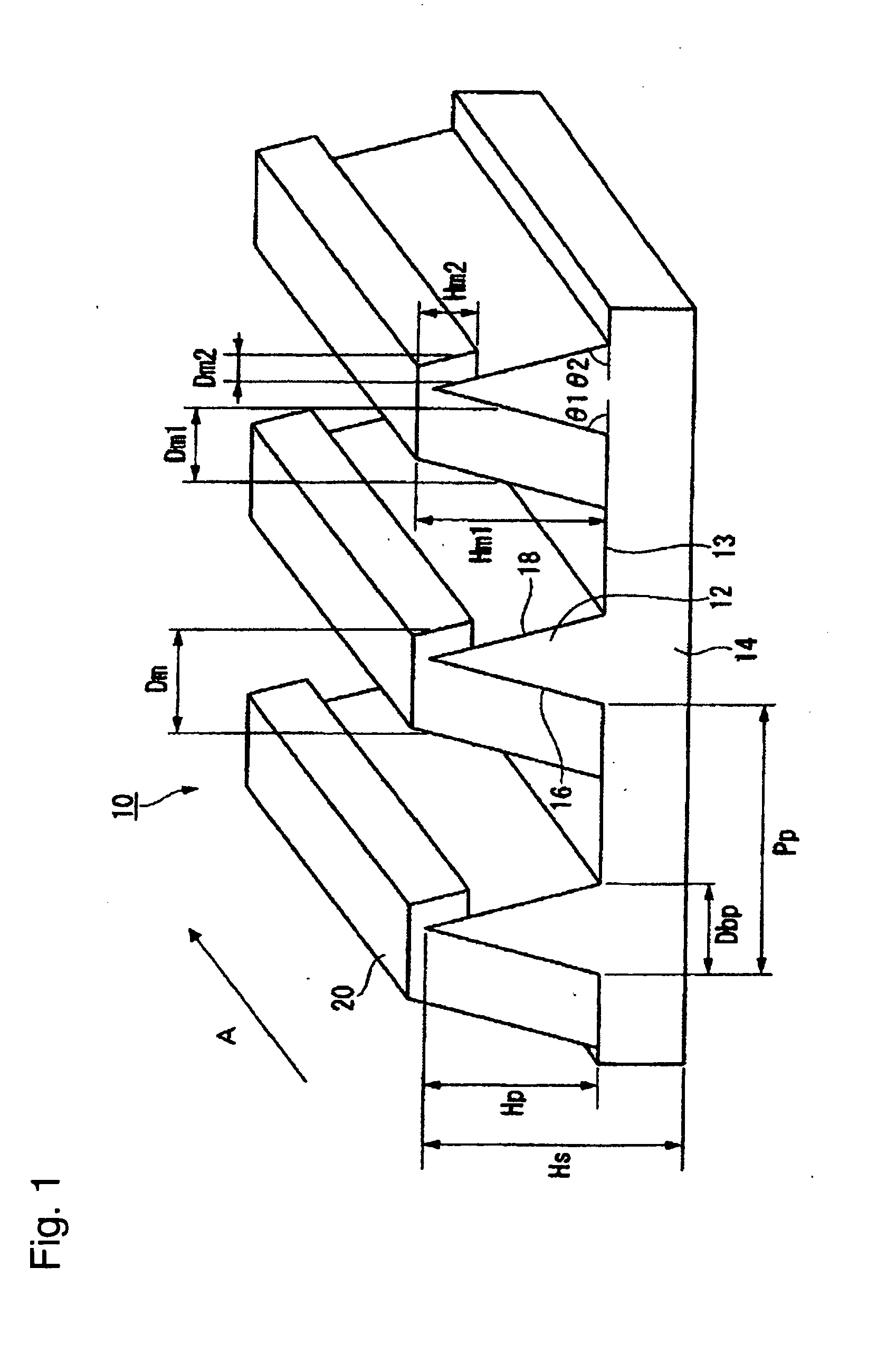
[0081]FIG. 1 is a perspective view showing the wire-grid polarizer according to a first embodiment of the present invention. The wire-grid polarizer 10 includes a light-transmitting substrate 14 having a plurality of ridges 12 formed in parallel to one another at certain pitches Pp through respective flat portions 13 disposed between adjacent ridges 12, each of the ridges extending in an direction indicated by an arrow A and having a triangular cross section; and a metal layer 20 composed of metal or a metal compound, the metal layer covering the entirety of a first lateral face 16 of each ridge 12, a part of the flat portion 13 adjacent to the first lateral face 16, between adjacent ridges 12, and a part of a second lateral face 18 of each ridge 12 adjacent to the first lateral face 16 such that the remaining part of the flat portion 13 and the remaining part of the second lateral face 18 are covered with no metal layer. The metal layer 20 extends in the longitudinal direction of e...

second embodiment

[0111]FIG. 3 is a perspective view showing the wire-grid polarizer according to a second embodiment of the present invention. The wire-grid polarizer 10 includes a light-transmitting substrate 14 having a plurality of ridges 12 formed in parallel to one another at certain pitches Pp through the flat portions 13 on the respective grooves disposed between adjacent ridges 12, each of the ridges having a trapezoidal cross section; and a metal layer 20 composed of metal or a metal compound, the metal layer covering the entirety of a first lateral face 16 of each ridge 12, a part of the flat portion 13 adjacent to the first lateral face 16, between adjacent ridges 12, the entirety of a top portion 19 of each ridge 12 adjacent to the first lateral face 16, and a part of a second lateral face 18 of each ridge 12 adjacent to the top portion 19 such that the remaining part of the flat portion 13 and the remaining part of the second lateral portion 18 are covered with no metal layer. The metal...

example 1

Preparation of Light-Transmitting Substrate

[0132]A photocurable composition 1 was applied by a spin coating method on the surface of a highly transmitting polyethylene terephthalate (PET) film (manufactured by Teijin DuPont Films Japan Limited, Teijin Tetoron O3, 100 mm×100 mm) having a thickness of 100 μm to form a coating film of the photocurable composition 1 having a thickness of 5 μm.

[0133]A quartz mold, which had a plurality of grooves formed at certain pitches so as to extend in parallel to one another through the respective flat portions between adjacent grooves (area: 150 mm×150 mm, pattern area: 100 mm×100 mm, groove pitch Pp: 160 nm, groove width Dbp: 65 nm, groove depth Hp: 200 nm, groove length: 100 mm, cross-sectional shape of groove: substantially isosceles triangle), was pressed against the coating film of the photocurable composition 1 with 0.5 MPa (gauge pressure) and at 25° C. so as to be brought into contact with the coating film of the photocurable composition 1...


PUM

PropertyMeasurementUnit
heightaaaaaaaaaa
angleaaaaaaaaaa
widthaaaaaaaaaa

Abstract

Provided are a wire-grid polarizer, which has not only a high degree of polarization, a high p-polarized light transmittance and a high s-polarized light reflectance but also a low angle dependency and a low wavelength dependency in terms of optical properties in a visible light region, and a process for producing the same.A wire-grid polarizer 10 comprising a light-transmitting substrate 14 having a plurality of ridges 12 formed in parallel to one another at certain pitches Pp through respective flat portions 13 disposed between adjacent ridges 12, each of the ridges having a width gradually reduced from a base portion to a top portion thereof, and a metal layer 20 composed of metal or a metal compound, the metal layer covering the entirety of a first lateral face 16 of each ridge 12 and a part of the flat portion 13 adjacent to the first lateral face 16 such that a second lateral face 18 of each ridge 12 is covered with no metal layer or is partially covered with the metal layer; and a process for forming the metal layer 20 by vapor-depositing metal or a metal compound on the first lateral face from a direction that is substantially orthogonal to a longitudinal direction of the ridges 12 and forms an angle of from 25 to 40 degrees toward the first lateral face 16 with respect to a height direction of the ridge 12 under conditions where the metal layer is disposed at a deposition amount of from 40 to 60 nm.

Description

TECHNICAL FIELD[0001]The present invention relates to a wire-grid polarizer and a process for producing the same.BACKGROUND ART[0002]As polarizers (also referred to as polarization splitters) used for image display devices, such as liquid crystal display devices, rear-projection televisions and front projectors, and showing a polarization separation ability in a visible light region, there are absorptive polarizers and reflective polarizers.[0003]An absorptive polarizer is, for example, a polarizer having a dichroic dye, such as iodine, aligned in a resin film. Such an absorptive polarizer has a low light use efficiency because of absorbing one of polarized light waves.[0004]On the other hand, a reflective polarizer has a higher light use efficiency since light that has been reflected without entering the polarizer is allowed to enter. For this reason, a demand for such a reflective polarizer is growing for the purpose of increasing the luminance of e.g. liquid crystal display devic...

Claims


Application Information

Patent Timeline
Patent Type & Authority Applications(United States)
IPC IPC(8): G02B5/30C08J7/04B05D5/06
CPCG02B5/3058G02B5/30G02F1/1335
Inventor KAIDA, YURIKOSAKAMOTO, HIROSHIMIYAGI, TAKAHIRASAKURAI, HIROMIIKEDA, YASUHIROSHIDOJI, EIJI
Owner ASAHI GLASS CO LTD
Why Eureka
Try Eureka