Inverter device and drive unit using the same

a technology of inverter device and drive unit, which is applied in the direction of electrical devices, electrical apparatus construction details, transportation and packaging, etc., can solve the problems of failure or malfunction, affecting etc., and achieve the effect of improving the heat dissipation performance of power elements

Active Publication Date: 2011-11-24
DENSO CORP
View PDF6 Cites 44 Cited by
  • Summary
  • Abstract
  • Description
  • Claims
  • Application Information

AI Technical Summary

Benefits of technology

[0025]The inverter device according to the present invention can improve the heat dissipation performance of the power elements. Therefore, for example, it is specifically effective to apply the inverter device according to the present invention to a high-power motor drive unit for an electric power steering system.

Problems solved by technology

Therefore, heats generated by adjacent power elements interfere with each other, thereby hindering heat dissipation.
Therefore, there is a possibility that a failure or malfunction due to temperature increase of the power elements is caused.

Method used


Image

  • Inverter device and drive unit using the same
  • Inverter device and drive unit using the same
  • Inverter device and drive unit using the same

Examples


first embodiment

[0057](First Embodiment)

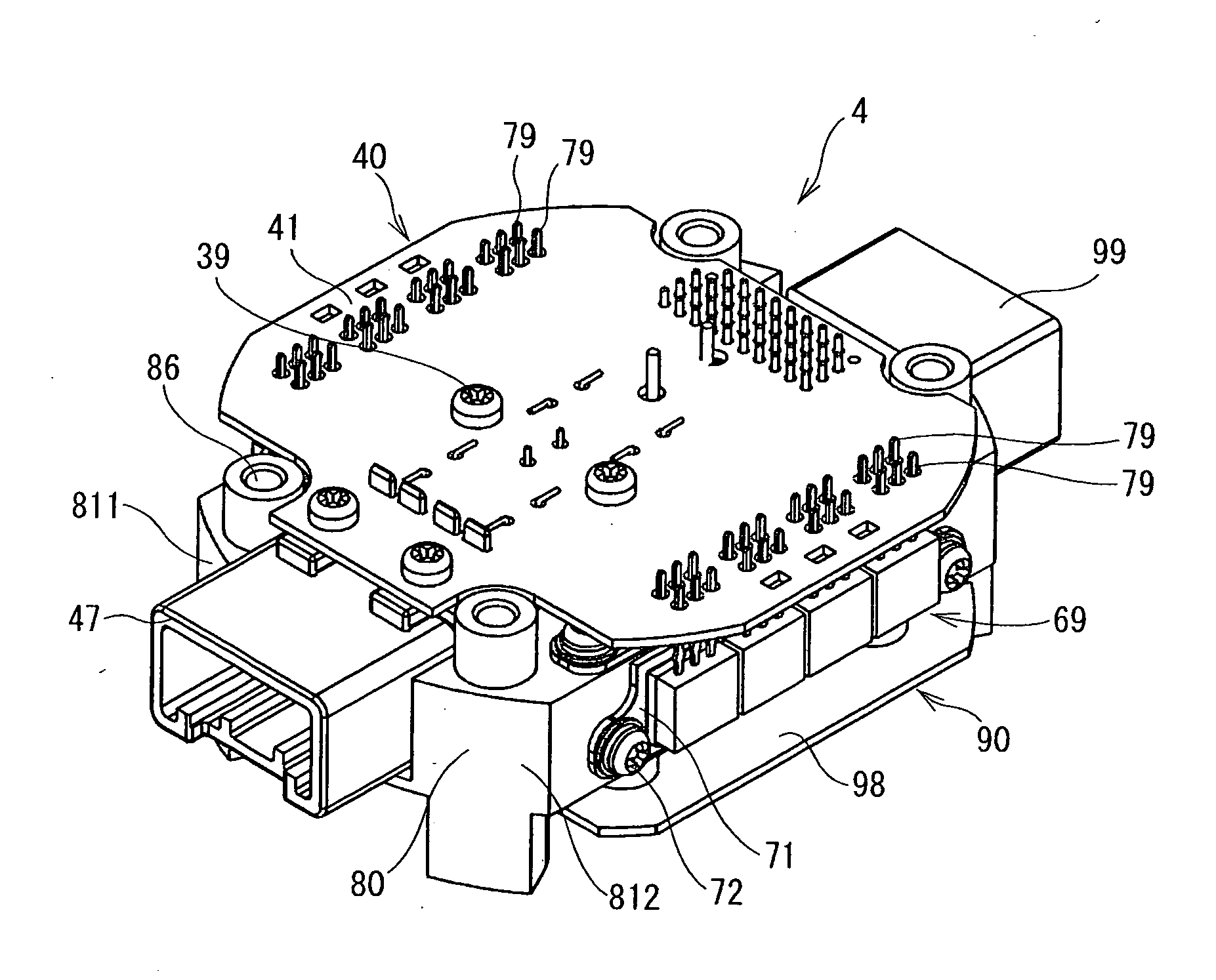
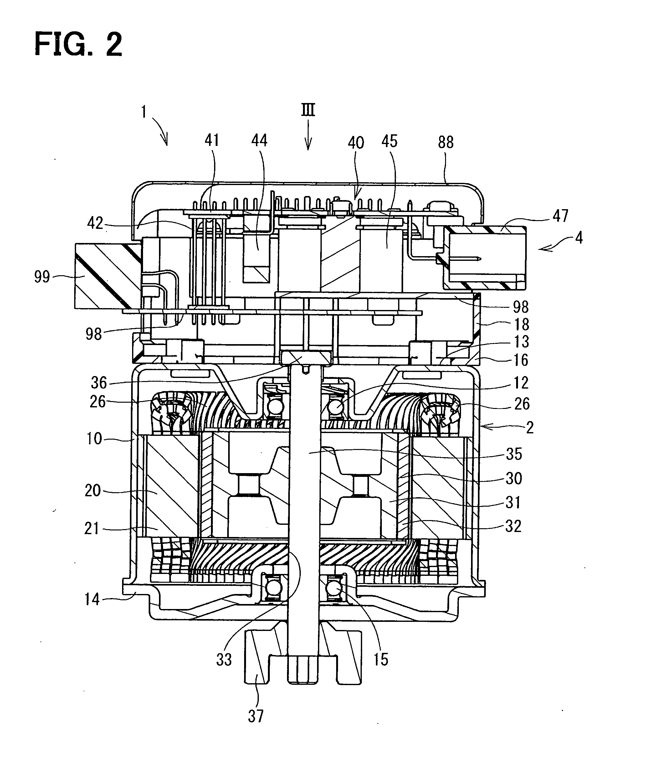
[0058]An inverter device according to a first embodiment of the present invention and a drive unit using the same are shown in FIGS. 1 to 18. The drive unit 1 according to the present embodiment is applied to an electric power steering system. The drive unit 1 has a motor 2 and the inverter device 4. The inverter device 4 consists of a control board assembly 90, a heat sink 80, multiple power elements mounted on the heat sink 80, a power substrate assembly 40 and the like. The control board assembly 90 corresponds to the control wiring section according to the present invention. The power substrate assembly 40 corresponds to the power wiring section according to the present invention.

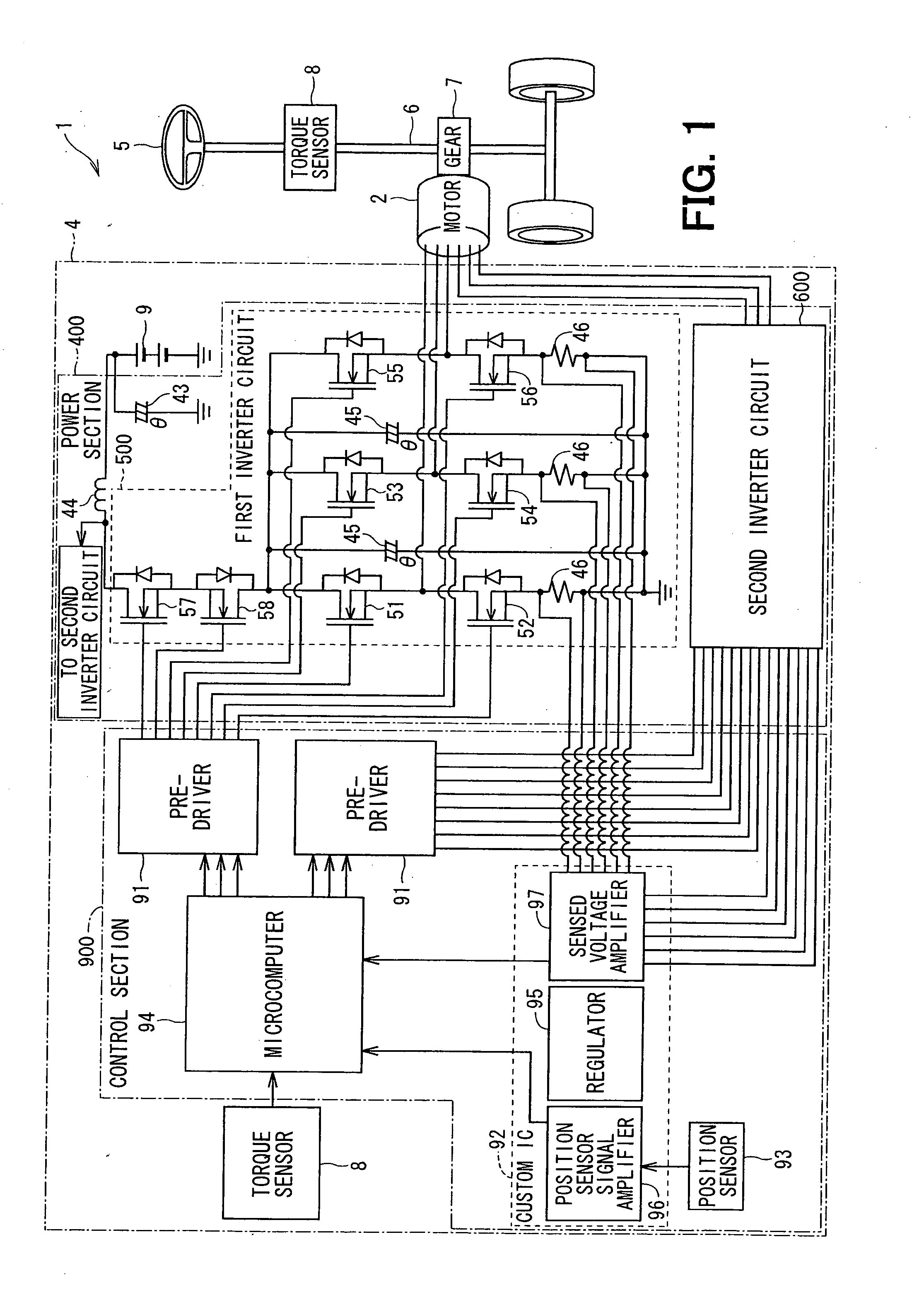
[0059]First, an electric construction of the electric power steering system will be explained with reference to FIG. 1. The electric construction explained below is commonly used also in the subsequent embodiments. As shown in FIG. 1, the drive unit 1 generates rotation torque in...

second embodiment

[0117](Second Embodiment)

[0118]Next, an inverter device according to a second embodiment of the present invention will be explained with reference to FIGS. 19 to 21. The inverter device 3 according to the second embodiment is applied to a single system of drive unit. The upper arm unit 50 consisting of the power elements 51-54 is attached to the outside surface 831 of one heat dissipation block 811 of the heat sink 80. The lower arm unit 59 consisting of the power elements 55-58 is attached to the outside surface 832 of the other heat dissipation block 812 of the heat sink 80. In this way, the upper arm unit 50 and the lower arm unit 59 are arranged on different planes. The second embodiment exerts the effects (1) to (4), (6) and (7) of the first embodiment.

third embodiment

[0119](Third Embodiment)

[0120]Next, an inverter device according to a third embodiment of the present invention will be explained with reference to FIGS. 22 to 24. The inverter device according to the third embodiment is applied to two systems of drive units. Differently from the first embodiment, the power elements 51-58, 61-68 are not mounted on the unit bases. The power elements51-58, 61-68 are attached to the heat sink 80 individually by screws 73 or an adhesive.

[0121]In this case, if the power elements, whose drain electrodes are exposed, are attached directly to the heat sink 80, the power elements short-circuit with each other. Therefore, it is necessary to interpose an insulation sheet 74 between the drain electrode 78 and the heat sink 80. The insulation sheet 74 is a thin plate made of an insulative material such as silicon. Alternatively, power elements having drain electrodes coated and insulated by a resin may be used. The third embodiment exerts the effects (1) to (5) ...


PUM


Abstract

In two systems of three-phase alternating-current inverter devices that drive a motor, power elements on power supply sides of bridge circuits are mounted on unit bases to constitute upper arm units. Power elements on ground sides of the bridge circuits are mounted on unit bases to constitute lower arm units. The upper arm units and the lower arm units are arranged separately on upper surfaces and outside surfaces of heat dissipation blocks of a heat sink. Heats generated by the power elements do not interfere with each other and are emitted to the heat sink, whereby heat dissipation performance of the power elements constituting the bridge circuits is improved.

Description

CROSS REFERENCE TO RELATED APPLICATION[0001]This application is based on and incorporates herein by reference Japanese Patent Application No. 2010-117682 filed on May 21, 2010.BACKGROUND OF THE INVENTION[0002]1. Field of the Invention:[0003]The present invention relates to an inverter device that produces multiple-phase alternating-current power from direct-current power and to a drive unit using the inverter device.[0004]2. Description of Related Art:[0005]Conventionally, an electric power steering system for assisting steering, which is performed by a driver, has been publicly known. An inverter device that produces alternating-current power from direct-current power is used as a controller for controlling drive of a motor in the electric power steering system. The inverter device is constructed by mounting electronic components such as semiconductor power devices such as transistors, resistors and capacitors on a power substrate. For example, a control unit and an electric power ...

Claims


Application Information

Patent Timeline
Patent Type & Authority Applications(United States)
IPC IPC(8): H05K7/20
CPCB60L2210/46B60L2220/58Y02T10/7241H05K7/209Y02T10/641H02M7/003Y02T10/64Y02T10/72
Inventor ABE, TATSUYAYAMASAKI, MASASHI
Owner DENSO CORP
Why Eureka
Try Eureka