
Surface light source device

a light source device and surface technology, applied in the direction of lighting and heating apparatus, planar/plate-like light guides, instruments, etc., can solve the problem of easy leakage of light from the inclined surface, and achieve the effect of reducing the leakage of light from the light introducing part, easy manufacturing, and increasing light use efficiency

Active Publication Date: 2011-11-24
TOHOKU DENSHI CO LTD
View PDF4 Cites 50 Cited by
  • Summary
  • Abstract
  • Description
  • Claims
  • Application Information

AI Technical Summary

Benefits of technology

[0062]One or more embodiments of the present invention may provide a surface light source device in which an end face of a light introducing part has a thickness approximately equal to the height of a light exit window of a point light source, thereby allowing light to be guided to a light guide plate thinner compared with the height of the light exit window of the point light source, in which leakage of light from the light introducing part is more decreased to increase light use efficiency and the device has a light guide plate shape that is easy to manufacture.
[0064]The inclination angle of the inclined surface is decreased so that light in the light introducing part does not leak from the inclined surface when entering the inclined surface for a first time. When the thickness of the light guide plate body is made thinner, light entering the inclined surface for a second time occurs, and the light is prone to leak from the inclined surface when entering for the second time. By contrast, one or more embodiments of the present invention has the structure described above. Therefore, by being reflected from the directivity conversion pattern, the light entering for the second time can be made less prone to leak from the inclined surface, thereby improving efficiency of the surface light source device.
[0065]In the surface light source device according to one or more embodiments of the present invention, the directivity conversion pattern is formed on the inclined surface, and an inclination angle frequency distribution of the directivity conversion pattern in a region positioned between an upper end edge and a lower end edge of the inclined surface and having a width equal to the light-emitting surface of the light source has a frequency in a range of inclination angles equal to or larger than 15.5° and equal to or smaller than 43.5° occupying 50% or more of a total. Note that the width of the light-emitting surface of the light source is a light-emitting width of the light source itself, and not the width of an LED chip or the like. According to one or more embodiments, efficiency of the surface light source device having a directivity conversion pattern formed on the inclined surface can be increased.
[0066]In the surface light source device according to one or more embodiments of of the present invention, the directivity conversion pattern is formed on a surface opposite to the inclined surface of the light guide plate, and an inclination angle frequency distribution of the directivity conversion pattern in a region between a position shifted from the upper end of the inclined surface to a side opposite to the light source by T·tan (90°−α−2θ) and a position shifted from a lower end of the inclined surface to the side opposite to the light source by t·tan (90°−α−2θ) (where T is a maximum thickness of the light introducing part, and t is a thickness of the light guide plate body, α is a critical angle of total reflection of a light guide plate material, and θ is the inclination angle of the inclined surface) when viewed from a direction perpendicular to the light exit surface, and the region also having a width equal to the light-emitting surface of the light source, has a frequency in a range of inclination angles equal to or larger than 15.5° and equal to or smaller than 43.5° occupying 50% or more of a total. According to one or more embodiments of the present invention, efficiency of the surface light source device having a directivity conversion pattern formed on a surface opposite to the surface where the inclined surface of the light guide plate is provided can be increased.
[0067]In the surface light source device according to one or more embodiments of of the present invention, the directivity conversion pattern has a depth and height constant with respect to a surface of the inclined surface. According to one or more embodiments, the light amount emitted from the light source and not entering the light introducing part to become a loss can be reduced, thereby improving light use efficiency.
[0068]In the surface light source device according to one or more embodiments of the present invention, the directivity conversion pattern is formed of recessed or projecting unit patterns, and when viewed from a direction perpendicular to the light exit surface, the unit patterns extend in a direction perpendicular to the light incident surface and are arranged in parallel to each other in a direction parallel to the light-emitting surface. According to one or more embodiments, light entering from the light incident surface can be guided approximately straight as it is. Also, the directivity conversion pattern can be easily fabricated.

Problems solved by technology

When the thickness of the light guide plate body is made thinner, light entering the inclined surface for a second time occurs, and the light is prone to leak from the inclined surface when entering for the second time.

Method used


Image

  • Surface light source device
  • Surface light source device
  • Surface light source device

Examples


first embodiment

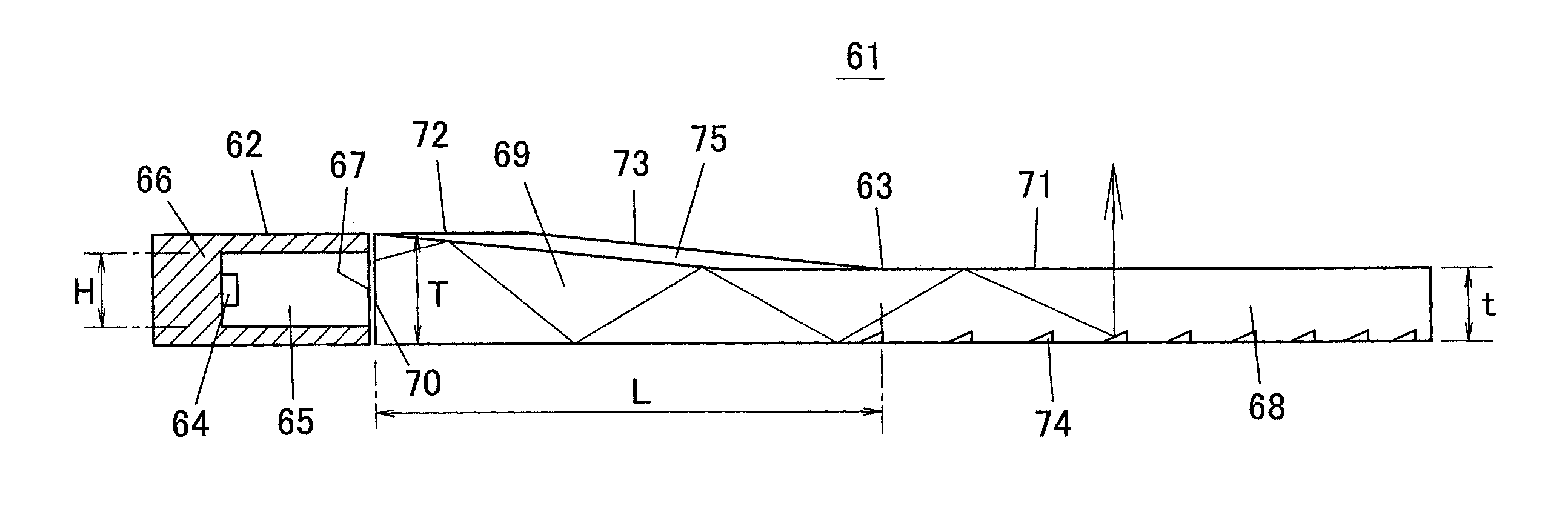
[0134]A surface light source device according to a first embodiment of the present invention is described. FIG. 10 is a perspective view of a surface light source device 61 according to the first embodiment of the present invention, and FIG. 11 is a schematic sectional view thereof. The surface light source device 61 includes a point light source 62 and a light guide plate 63. The point light source 62 has one or plurality of LEDs incorporated therein, and emits white light. A LED 64 is sealed in a transparent sealing resin 65. Furthermore, the transparent sealing resin 65 is covered with a white resin 66 except the front, and the front of the transparent sealing resin 65 exposed from the white resin 66 serves as a light exit window 67 (a light-emitting surface). This point light source 62 is small compared with the width (or the dimension in a depth direction on paper in FIG. 11) of the light guide plate 63, and is thus called a point light source, in contrast to a cold-cathode-flu...

second embodiment

[0197]FIG. 42A is a perspective view of a surface light source device 91 according to a second embodiment of the present invention, and FIG. 42B is a side view thereof. The surface light source device 91 of the second embodiment has a feature in which an upper end of the V grooves 76 configuring the directivity conversion pattern 75 does not reach an end of the horizontal surface 72 on a light incidence end face side. According to this embodiment, because the horizontal surface 72 remains between the upper end of the V grooves 76 and the light incidence end face 70, a metal mold for molding the light guide plate 63 can be easily manufactured.

third embodiment

[0198]FIG. 43 is a perspective view of a surface light source device 92 according to a third embodiment of the present invention. The surface light source device 92 of the third embodiment has a feature in which the directivity conversion pattern 75 is provided not only in a region immediately before the point light source 62 but over the entire width of the the inclined surface 73 and the horizontal surface 72. According to this embodiment, the point light source 62 can be placed at an arbitrary position along the light incidence end face 70. Therefore, versatility of the light guide plate 63 can be achieved, and it is possible to eliminate the need of redesigning the light guide plate 63 depending on the number or position of the point light source, or remanufacturing a metal mold for molding.

[0199]In the case of this embodiment, in place of a point light source, a linear light source can be used, such as a cold-cathode tube.


PUM


Abstract

A light guide plate is formed of a light introducing part positioned to face a point light source for confining light and a light guide plate body having a thickness smaller than the thickness of an end of the light introducing part on a point light source side and causing the confined light to be output from a light exit surface to outside. The light introducing part has an inclined surface, and a directivity conversion pattern formed on the inclined surface. The directivity conversion pattern is configured by arranging V grooves in parallel to each other, each having a vertical angle of 120°, and each extends in a direction approximately perpendicular to a light incidence end face of the light guide plate. The length of the inclined surface in a inclination direction where part of light incident to the light introducing part enters the inclined surface at least twice.

Description

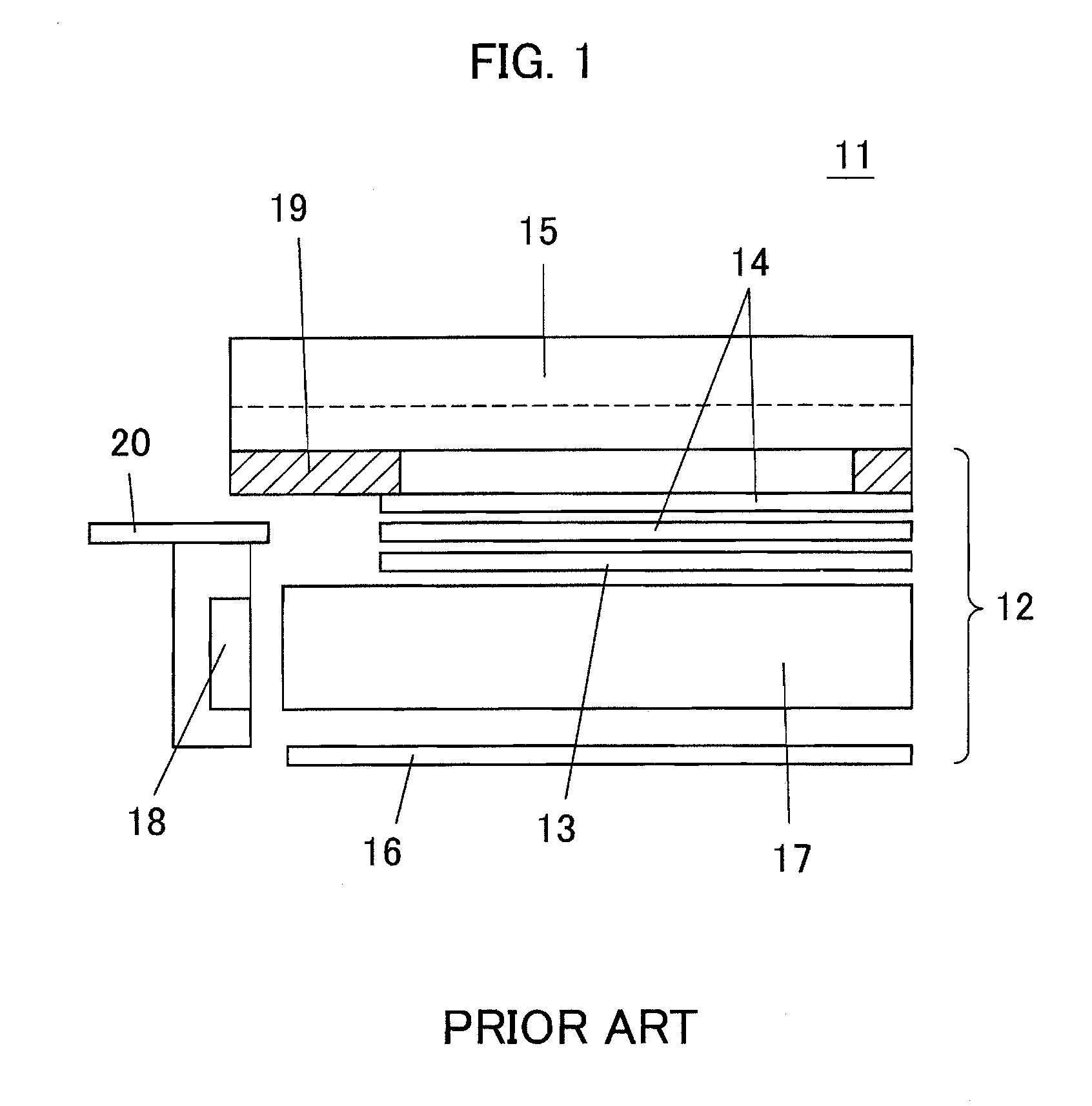
BACKGROUND OF INVENTION[0001]1. Technical Field[0002]One or more embodiments of the present invention relate to a surface light source device and, more particularly to the structure of a surface light source device for letting light efficiently enter a light guide plate thinner than the thickness of a light source.[0003]2. Background Art[0004]FIG. 1 is a schematic diagram of a conventional liquid-crystal display device using an edge-light type surface light source device. This liquid-crystal display device 11 is configured of a surface light source device 12 and a liquid crystal panel 15.[0005]In the surface light source device 12, a point light source 18 using an LED is disposed so as to face an end face (a light incidence surface) of a light guide plate 17 molded of transparent resin, a diffusion plate 13 and two prism sheets 14 are stacked on an upper surface (a light exit surface) of the light guide plate 17, and a reflecting plate 16 faces a lower surface of the light guide pla...

Claims


Application Information

Patent Timeline
Patent Type & Authority Applications(United States)
IPC IPC(8): F21V8/00
CPCG02B6/0016G02B6/0018G02B6/002G02F1/133615G02B6/0028G02B6/0031G02B6/0038G02B6/0021G02F1/1335G02B6/00G02B6/0001
Inventor TANOUE, YASUHIROKURATA, GOUOSHINOHARA, MASAYUKI
Owner TOHOKU DENSHI CO LTD
Learn More