Substrate made of porous metal or metal alloy, preparation method thereof, and hte or sofc cells with a metal support comprising this substrate

a technology of porous metal or metal alloy, which is applied in the direction of cell components, final product manufacturing, sustainable manufacturing/processing, etc., can solve the problem of insatiable resistance to oxidation of porous material for sofc applications, and achieve the effect of reducing the cost of metal-supported cells

Active Publication Date: 2011-11-24
COMMISSARIAT A LENERGIE ATOMIQUE ET AUX ENERGIES ALTERNATIVES
View PDF1 Cites 45 Cited by
  • Summary
  • Abstract
  • Description
  • Claims
  • Application Information

AI Technical Summary

Benefits of technology

[0058]5°) the support should be inexpensive, one of the goals being to reduce the cost of metal-supported cells as compared with other types of cells;

Problems solved by technology

Document [8] reports a tubular porous metal support made by isostatic pressing, doubtless because the tubular geometry does not allow strip casting.
A porosity of 40% is indicated, and the conclusion is drawn that the resistance to oxidation of this porous material is not satisfactory for an SOFC application.
In none of documents cited above, is mentioned the question of optimizing the porous metal support for promoting adherence, anchoring of the ceramic layers, while this is a crucial problem for proper operation of an SOFC-HTE cell.

Method used


Image

  • Substrate made of porous metal or metal alloy, preparation method thereof, and hte or sofc cells with a metal support comprising this substrate
  • Substrate made of porous metal or metal alloy, preparation method thereof, and hte or sofc cells with a metal support comprising this substrate
  • Substrate made of porous metal or metal alloy, preparation method thereof, and hte or sofc cells with a metal support comprising this substrate

Examples


example 1

[0210]60 porous metal supports with a thickness of 1.6 mm and a diameter of 25 mm are prepared by pressing a powder of alloy 1.4509 sifted to 50-100 μm and then by sintering.

[0211]The sintering is carried out at 1,200° C. for 3 hours under a controlled atmosphere (Ar+2%H2) in the following way:

[0212]A temperature rise at a rate of 200° C. / hour up to 500° C., and then a 1 hour plateau at 500° C. for promoting binder removal, and then a new rise in temperature at a rate of 300° C. per hour up to 1,200° C., and then again a 3 hour plateau at 1,200° C., and lowering of the temperature at a rate of 300° C. per hour down to room temperature.

[0213]The porosity obtained after sintering (measured by volume density and pycnometry) is from 27% to 30%.

example 2

[0214]30 porous metal supports with a thickness of 3 mm and a diameter of 25 mm are prepared by pressing-sintering of a powder of alloy 1.4509. The powder is the same powder as the one of Example 1, obtained by atomization. The porosity after sintering is 27%.

example 3

[0215]A porous metal support with a thickness of 1.6 mm and a diameter of 25 mm is prepared by pressing-sintering with the same alloy powder as the one of Examples 1 and 2.

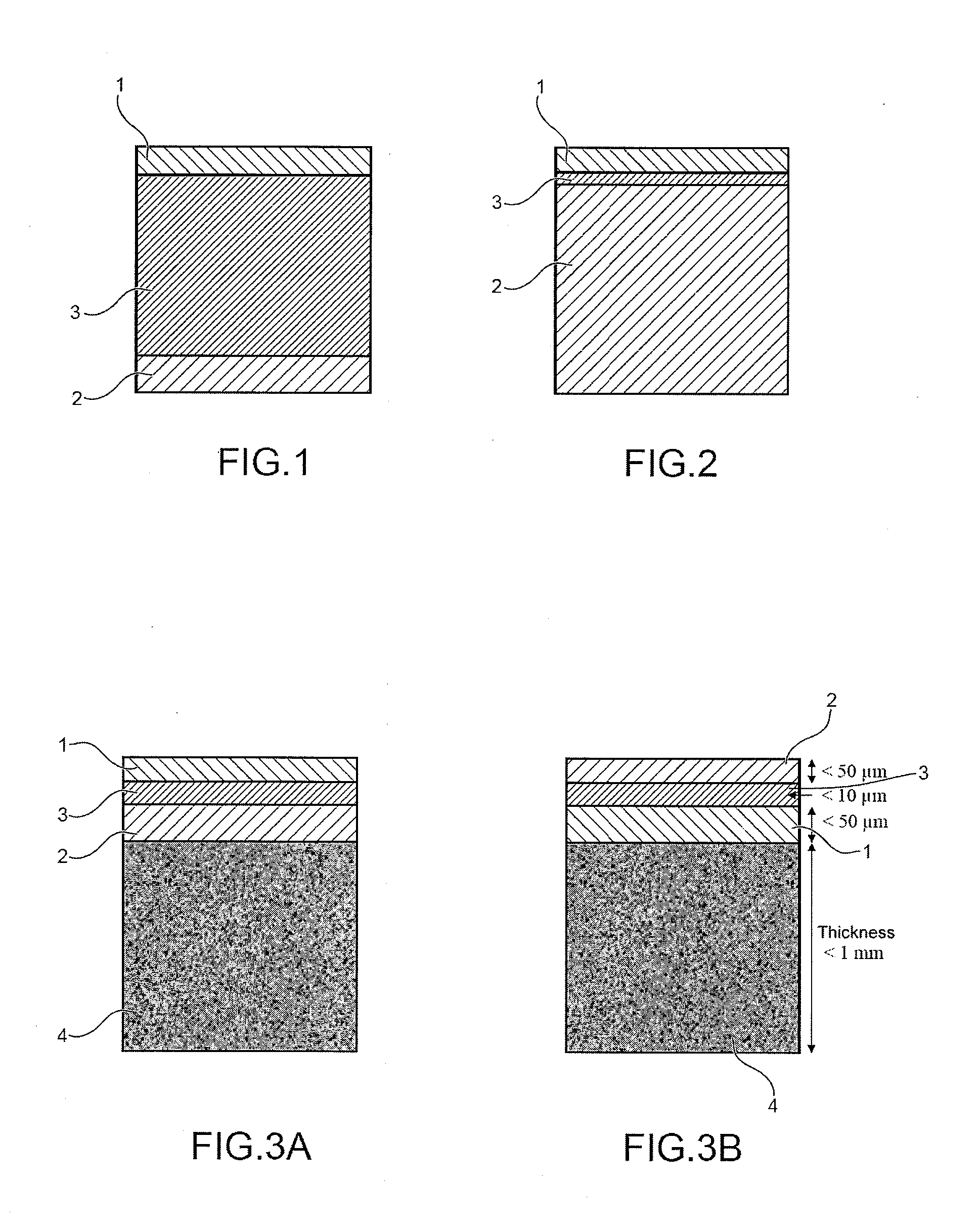
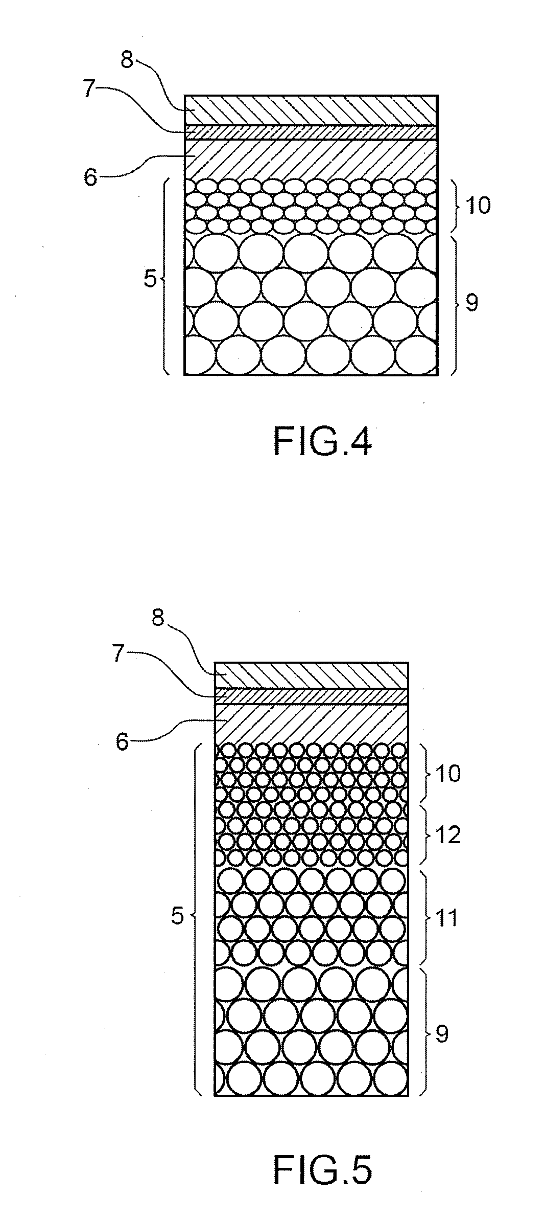
[0216]The support has a porosity gradient with a lower sub-layer, with a thickness of 1 mm, and an upper sub-layer with a thickness of 0.6 mm.

[0217]The lower sub-layer has a porosity from 30% to 40%, a grain size from 100 μm to 200 μm, and a pore size from 30 μm to 40 μm.

[0218]The upper sub-layer has a porosity from 20% to 30%, a grain size from 10 μm to 50 μm, and a pore size from 5 μm to 10 μm.

[0219]Both sub-layers are co-sintered according to the procedure described in Example 1.

[0220]A layer permeation of 4.3.10−14 m2 is obtained.


PUM

PropertyMeasurementUnit
temperatureaaaaaaaaaa
porosityaaaaaaaaaa
porosityaaaaaaaaaa

Abstract

A partly oxidized substrate, obtained by subjecting a substrate made of a porous metal or metal alloy comprising particles of at least one metal or metal alloy bound by sintering, said substrate comprising a first main surface and a second main surface, and said substrate having a porosity gradient from the first main surface to as far as the second main surface; to partial oxidation by an oxidizing gas such as oxygen and/or air.
Method for preparing said substrate and high temperature electrolyzer cell (<<HTE>>) comprising said substrate.

Description

TECHNICAL FIELD[0001]The invention relates to a substrate made of porous metal or metal alloy.[0002]The invention further relates to a method for preparing this substrate by pressing-sintering.[0003]The invention finally relates to a high temperature electrolyzer cell (<<HTE>>) or a high temperature fuel cell (<<SOFC>> or <<Solid Oxide Fuel Cell>>), more specifically a high temperature electrolyzer cell or high temperature fuel cell with a metal support (<<MSC>> or <<Metal Supported Cell>> comprising said substrate.[0004]The technical field of the invention may thus be generally defined as that of new energy technologies, more particularly as that of high temperature electrolyzers and high temperature fuel cells and, even more specifically, as that of cells of high temperature electrolyzers and of high temperature fuel cells with a metal support.STATE OF THE PRIOR ART[0005]The first generation of high temperature electrolyz...

Claims


Application Information

Patent Timeline
Patent Type & Authority Applications(United States)
IPC IPC(8): H01M2/14H01M8/04B22F3/24C25B13/02B22F3/11B22F3/12B32B5/14C25B9/00
CPCC25B9/00H01M4/861H01M8/0232Y02E60/525H01M8/1286Y02E60/521H01M8/0245Y02E60/50Y02P70/50
Inventor MOUGIN, JULIEPIETRI, THOMAS
Owner COMMISSARIAT A LENERGIE ATOMIQUE ET AUX ENERGIES ALTERNATIVES
Why Eureka
Try Eureka