

Stationary Bubble Reactors
a technology of stationary bubble reactors and reactors, which is applied in the direction of liquid-gas reaction of thin-film type, moving filter element filters, fungi, etc., can solve the problems of reducing productivity, mixing becomes a serious challenge in larger vessels, and product degradation, so as to reduce production, increase gasification rate, and high energy
- Summary
- Abstract
- Description
- Claims
- Application Information
AI Technical Summary
Benefits of technology
Problems solved by technology
Method used
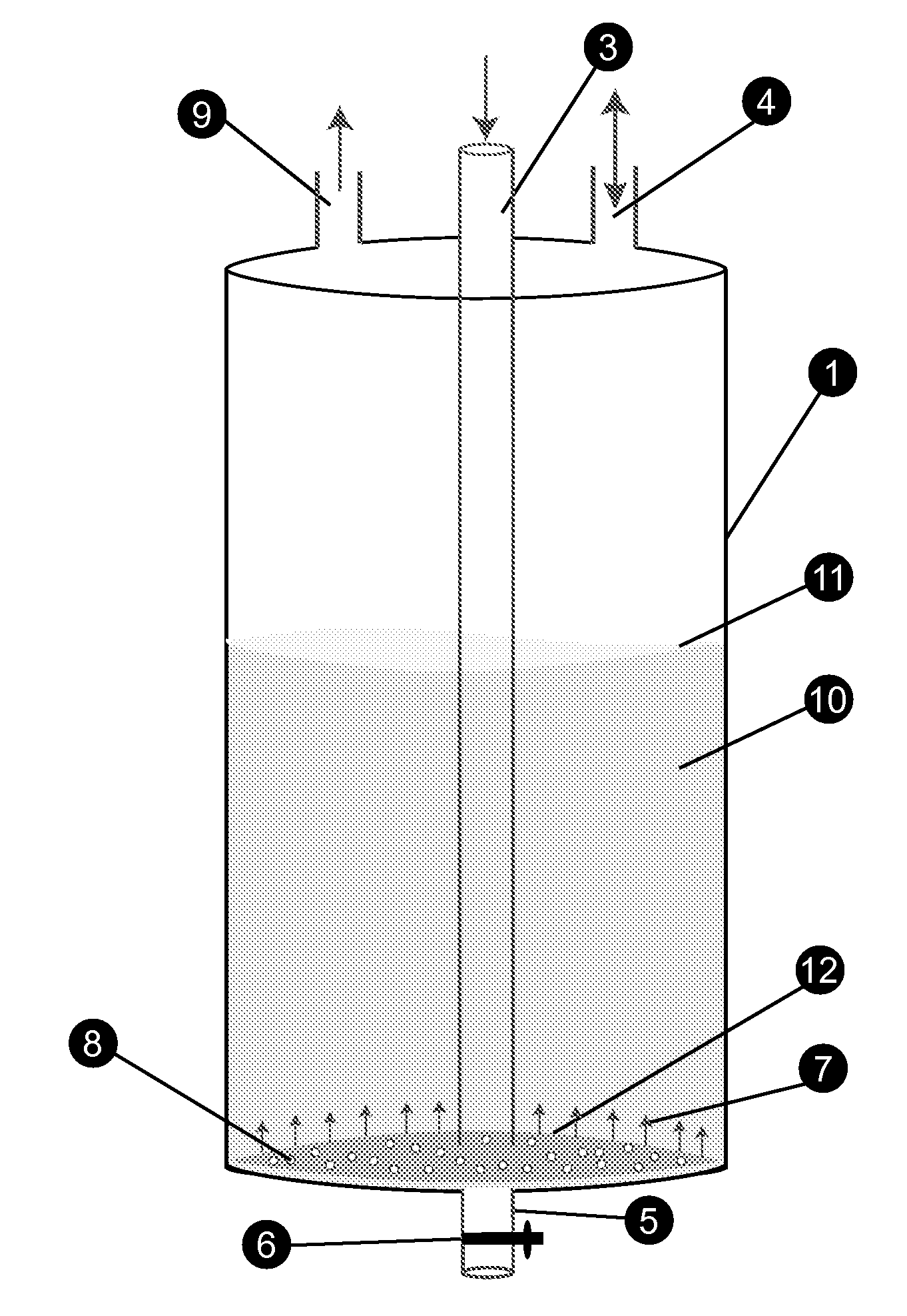
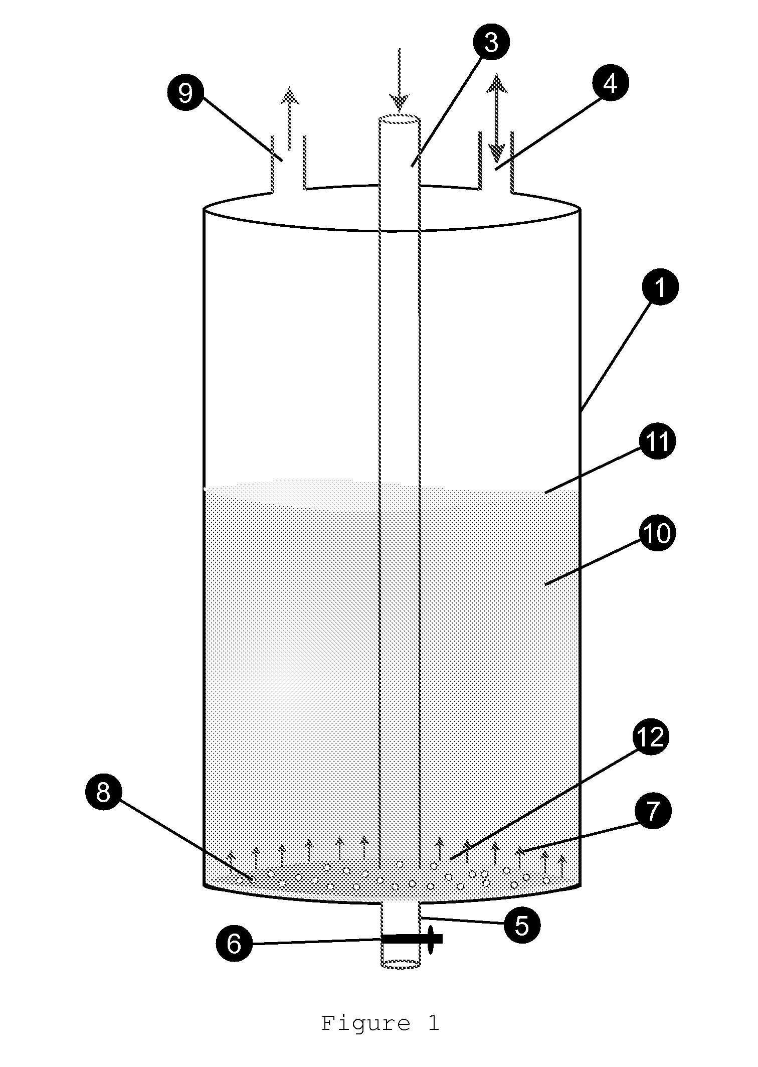
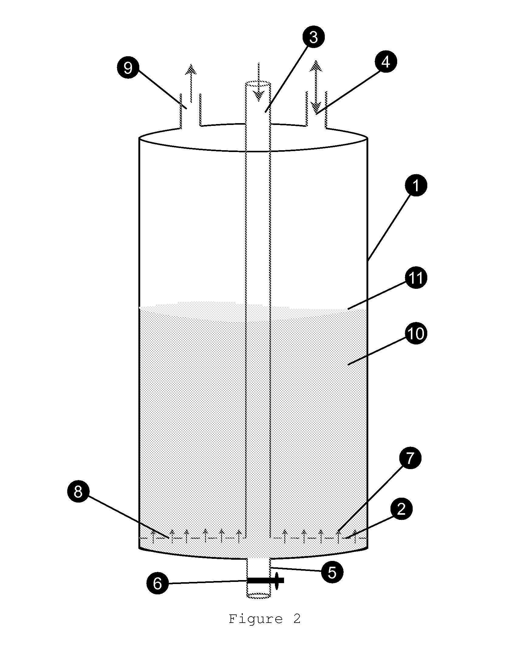
Image

Examples
Embodiment Construction
[0019]The instant invention addresses two critical problems in a variety of industries where liquids are mixed or gasified. Historically, an impeller device that rotates fast inside a liquid volume creates a circular movement to mix liquids. Since the energy transfer to liquids is highly efficient, this remains as the most widely used method. The goal of impellers is to create a large enough circle of movement that would cause the movement of entire liquid; in some designs larger size impellers achieve it or smaller size impellers achieve it by high velocity. A good example of this is found in the movement of boats. Large ships have impellers that move at a very slow speed but displace a very large volume of liquid while the onboard motors on smaller boats have a very small fan that rotates at a very high speed. In liquid mixing, often the containers have baffles to break the laminar movement of liquid generated by the circular motion of the impeller to increase the mixing efficienc...
PUM
| Property | Measurement | Unit |
|---|---|---|
| size | aaaaa | aaaaa |
| inner volume | aaaaa | aaaaa |
| shape | aaaaa | aaaaa |
Abstract
Description
Claims
Application Information