
Counterflow burning type coal gasifier device and process thereof

A technology of coal gasification and reverse combustion, which is applied in the chemical industry, petroleum industry, and the manufacture of combustible gas, etc., and can solve problems such as phenol water pollution

Active Publication Date: 2014-03-19
淄博硕丰环保设备有限公司
View PDF6 Cites 4 Cited by
  • Summary
  • Abstract
  • Description
  • Claims
  • Application Information

AI Technical Summary

Problems solved by technology

[0003] The technical problem to be solved by the present invention is to provide a counter-burning type coal gasifier device and process in order to overcome the serious defect of phenolic water pollution in the gas station, and reintegrate the gas production principle and process flow of the two-stage gas furnace to realize In order to allow the combustible components and moisture in the coal to participate in the gas-making reaction, without the precipitation of phenol water and coal tar, all the elements in the coal are converted into gas, without the production of tar and phenol water, completely achieving clean gas production At the same time, the furnace temperature can be automatically controlled, avoiding the backward working method that can only rely on manual slag removal and the operator's work experience to adjust the furnace condition

Method used


Image

  • Counterflow burning type coal gasifier device and process thereof
  • Counterflow burning type coal gasifier device and process thereof
  • Counterflow burning type coal gasifier device and process thereof

Examples


Embodiment Construction

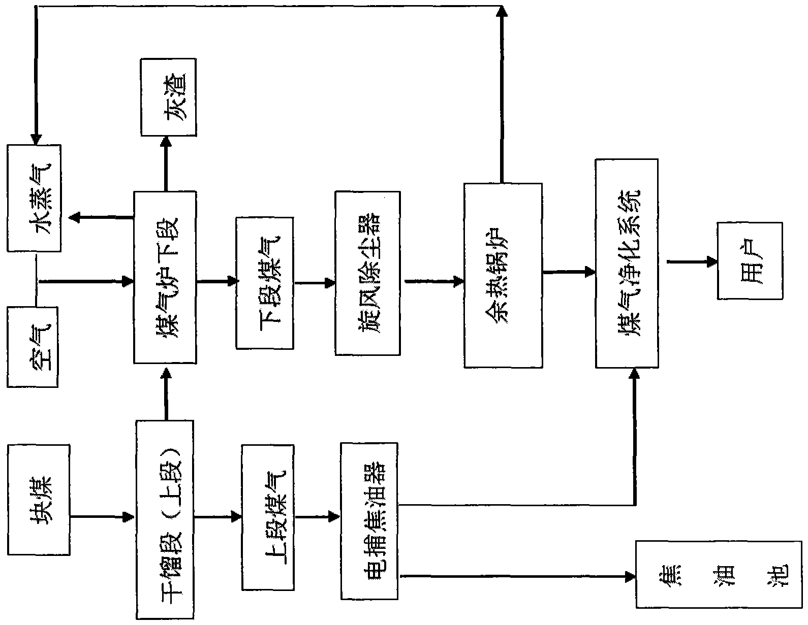
[0062] figure 1 It is a process schematic diagram of an existing two-stage gasifier, and its principle has been described in detail in the content of the invention.

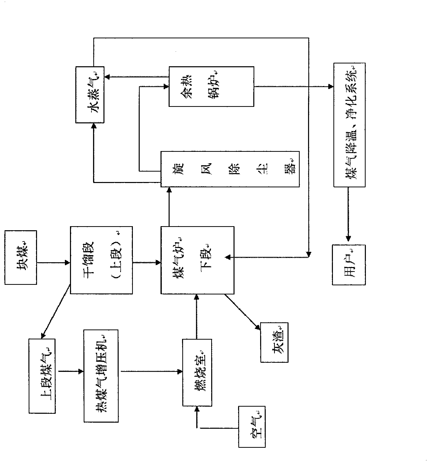
[0063] figure 2 It is a schematic diagram of the process of the present invention.

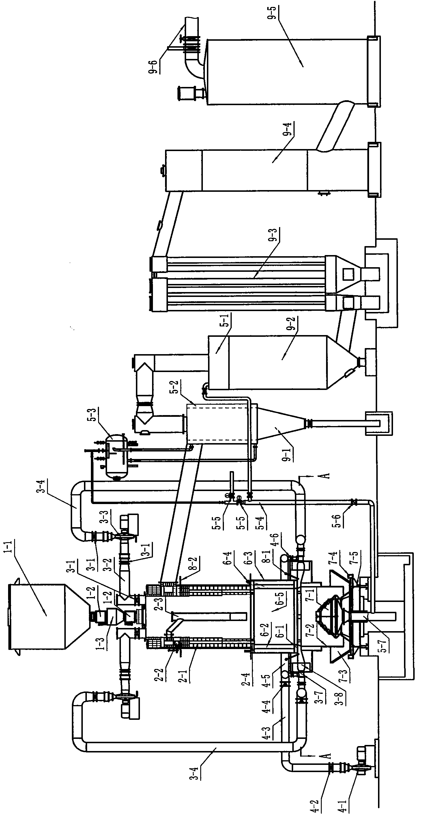
[0064] like image 3 , Figure 4 Shown: the device described in the present invention includes a coal adding system, a dry distillation system, an anti-burning heating system, a combustion-supporting air supply system, a steam supply system, a gas generation system, an ash removal system, an automatic temperature control system and a gas cooling system purification system.

[0065] 1) The coal feeding system of the present invention includes a coal bunker 1-1, two coal feeding valves 1-2 and a buffer coal bunker 1-3. Its structure is the same as that of the prior art and will not be described in detail.

[0066] 2) The retort system of the present invention includes a retort section furnace body, a retort section gas regula...


PUM


Abstract

The invention specifically relates to a novel counterflow burning type coal gasifier device and a process thereof. The device is composed of following nine major systems: a coal charging system, a dry distillation system, a counterflow burning heating system, a combustion supporting air supply system, a steam supply system, a gas generation system, an ash removal system, an automatic temperature control system and a gas cooling purification system; the process comprises the following steps: 1) generating upper section gas containing dry distillation gas, tar gas, phenol organic matter gasses and water steam; 2) feeding the upper section gas into a combustion chamber for combustion through a hot gas supercharger; 3) introducing high temperature gas generated after combustion in the combustion chamber and containing water vapor and CO2 into the hearth at the lower section of the coal gasifier to contact with coke, and generating to generate lower section gas; 4) cooling and separating dust from the generated lower section gas and then transmitting the gas to the user end. The device and the process provided by the invention are free of discharge of pollutants such as tar and carbolisata aqua, and have the advantages of high heat utilization rate, energy conservation and environmental friendliness; the generated gas is high in cleanness and combustion value.

Description

technical field [0001] The invention belongs to the field of gas production technology and equipment of a producer gas station, and in particular relates to a novel counter-burning type coal gasification furnace device and technology. technical background [0002] The technology of using coal to make gas has been applied in my country for decades, especially since the 1880s, with the development needs of my country's reform and opening up and the rapid development of industrial technology, the two-stage gas furnace imported from abroad The advanced gas production process has been widely promoted and applied in our country, and has been widely used in chemical industry, smelting, machinery manufacturing, building materials and other industries. However, with the growth of China's industrial level, the scale of use of gas furnaces is increasing, and the number is also increasing. The phenol water and tar produced in the process of gas production have also produced very serious ...

Claims


Application Information

Patent Timeline
IPC IPC(8): C10J3/20C10J3/58
CPCY02P20/10
Inventor 张秀军
Owner 淄博硕丰环保设备有限公司
Learn More