
Method for Flushing a Section of a Fuel System of a Gas Turbine

a technology of a fuel system and a gas turbine, which is applied in the direction of turbine/propulsion fuel valves, machines/engines, and cleaning using liquids. it can solve the problems of insufficient cleaning of the supply line, insufficient cleaning, and insufficient cleaning. the effect of the supply lin

Inactive Publication Date: 2011-12-01
SIEMENS AG
View PDF7 Cites 9 Cited by
  • Summary
  • Abstract
  • Description
  • Claims
  • Application Information

AI Technical Summary

Benefits of technology

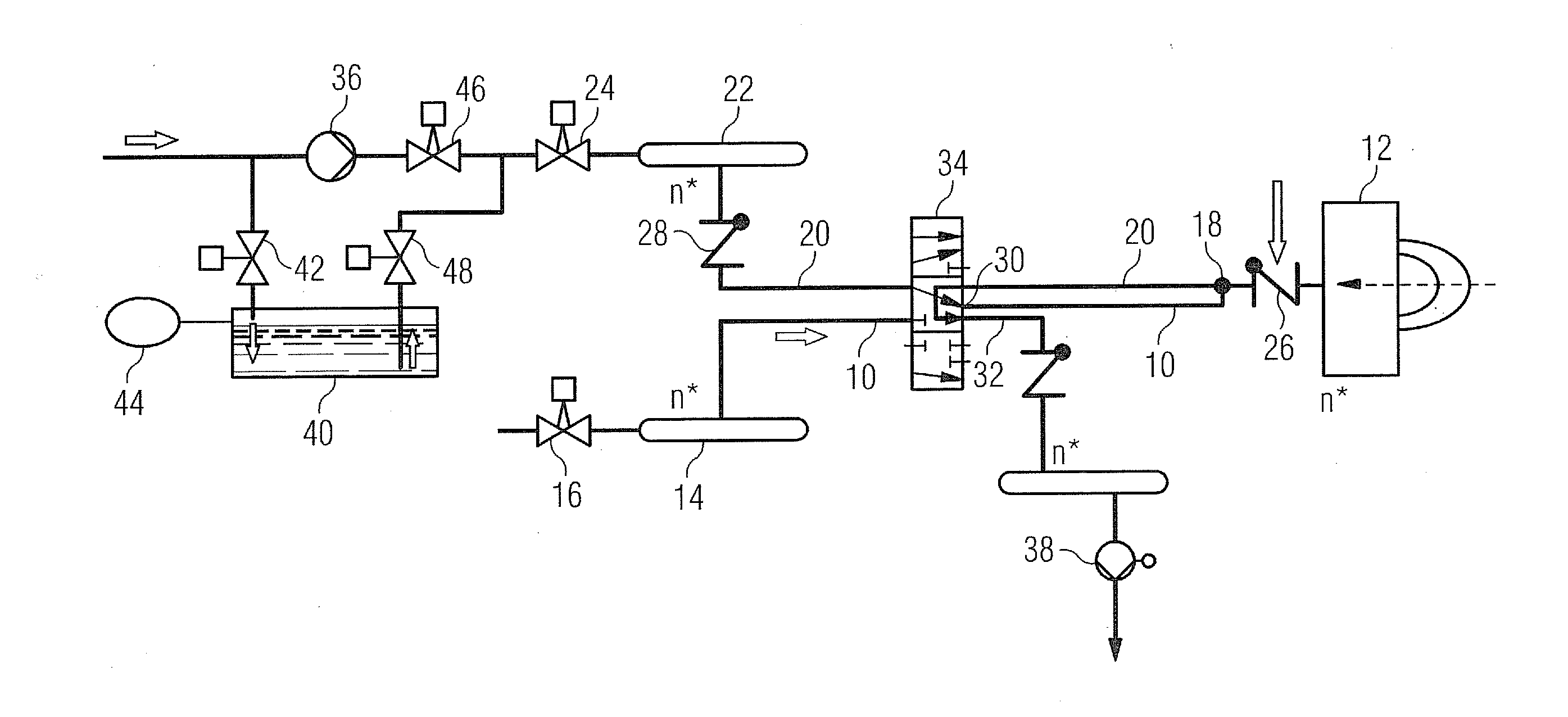
[0012]In a second advantageous development of the method according to the invention, the vacuum is generated at the second connection point by means of a suction or scavenging pump arranged in a drainage line. Since corresponding drainage lines are present in any case in known fuel systems, only a pump has to be inserted into an existing line for the purpose of this development. This not only has cost benefits in terms of plants newly to be installed, but also entails the advantage that the solution can be integrated simply and cost-effectively even in existing gas turbines.
[0013]In a third advantageous development of the method according to the invention, the medium is provided at the first connection point by means of a reservoir in which the pressure of the medium is maintained, in particular, at ambient pressure. The reservoir of this type may be configured cost-effectively in the manner of a tub or (open) tank and, in particular, does not have to have any pressure sealing. The reservoir should be arranged in a line which runs parallel to a delivery line of a water injection system with an injection pump arranged in it. The reservoir is then connected in parallel to said injection pump. Thus, selectively, the path through the injection pump (for the injection of medium, in particular water, for fuel oil / water emulsion operation) or the path through the reservoir (for the pressureless feed of medium during the flushing operation) can be set by means of a simple changeover valve.
[0014]In a fourth advantageous development of the method according to the invention, the medium used is water because of the abovementioned advantages. As mentioned, water is already present in gas turbines in the NOx water supply system there, by means of which, when the gas turbine is in operation, the water can be metered into the burner in order to reduce the emission of nitrogen oxides.
[0024]During normal combustion operation, medium can advantageously be fed in under pressure via the near-burner connection point by means of the multifunction valve. Furthermore, if appropriate, the nozzles on the burner can be flushed into the combustion chamber of the latter via the near-burner connection point. Furthermore, medium can be supplied pressurelessly via the connection point remote from the burner and sucked away into the drainage (as explained above). The multifunction actuating member of this type can be manufactured and also tested as a unit. Furthermore, it can be activated within the fuel system by means of only one line bundle, that is to say, overall, especially cost-effectively. Moreover, when the burner is operating normally, its actuating members shut off the fuel supply line with respect to the feed of extraneous medium.
[0025]The solution according to the invention thus makes it possible, overall, to have simple, cost-effective and at the same time especially effectively cleaning flushing of the supply line for fuel on a gas turbine.

Problems solved by technology

The method of this type overcomes the actual problem of known procedures which cannot ensure that fuel oil is forced into the burner or burners during flushing.

Method used


Image

  • Method for Flushing a Section of a Fuel System of a Gas Turbine
  • Method for Flushing a Section of a Fuel System of a Gas Turbine

Examples


Embodiment Construction

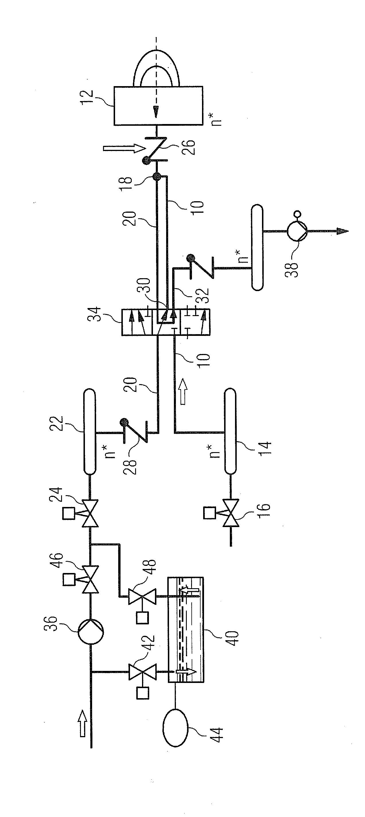
[0027]FIG. 1 illustrates a fuel system with a supply line 10 for supplying fuel or fuel oil to a burner 12 (a number n of burners 12 being present). The fuel is in this case fed into a fuel oil flow actuator 14 by means of an actuating member in the form of an actuating valve 16, from which it enters the supply line 10.

[0028]Formed near the burner 12, in the supply line 10, is a T-piece or connection point 18, at which a medium can be fed into the supply line 10 through a feed line 20. The medium is water which comes from a water distributor 22 of an NOx water supply system with an actuating valve 24 arranged upstream of it in the flow direction. In this case, a nonreturn valve 26 opening toward the burner 12 is provided in the supply line 10 between the connection point 18 and the burner 12 and a nonreturn valve 28 opening toward the connection point 18 is provided in the feed line 20.

[0029]Upstream of the connection point 18 in the flow direction is arranged, in the supply line 10...


PUM


Abstract

A fuel system of a burner of a gas turbine and to a method for flushing a section of a fuel system of a burner of a gas turbine is provided. The method includes providing a feed line for feeding liquid fuel from a fuel source to the burner, providing a first and a second connection point to the feed line, providing a medium at the first connection point and generating a vacuum at the second connection point such that the fuel which is situated in the section between the two connection points is sucked out through the second connection point.

Description

CROSS REFERENCE TO RELATED APPLICATIONS[0001]This application is the US National Stage of International Application No. PCT / EP2010 / 050708, filed Jan. 22, 2010 and claims the benefit thereof. The International Application claims the benefits of European Patent Office application No. 09001717.9 EP filed Feb. 6, 2009. All of the applications are incorporated by reference herein in their entirety.FIELD OF INVENTION[0002]The invention relates to a method for flushing a section of a fuel system of a burner of a gas turbine. The invention relates, furthermore, to a fuel system of a burner of a gas turbine with a supply line for supplying fuel from a fuel source to the burner.BACKGROUND OF INVENTION[0003]In gas turbines operating with fuel oil, the fuel oil or liquid fuel has to be removed, after operation, from the burners and from the delivery pipelines connected to them, in order to prevent carbonization of the fuel oil on their hot surfaces. Carbonization would block lines and burners a...

Claims


Application Information

Patent Timeline
IPC IPC(8): F02C7/232B08B3/00B08B5/04
CPCF02C7/232F23K5/04F05D2260/602F23K5/18F23K5/06Y10T137/0424
Inventor WAGNER, ULRICH
Owner SIEMENS AG
Learn More