
Method and apparatus for protection of trachea during ventilation

a technology for trachea and ventilation, applied in the direction of tracheal tubes, respirators, medical devices, etc., can solve the problems of insufficient suction of the pharynx, inability to ensure the complete removal of all secretions, and inability to implement sealing pressure in practice, so as to prevent leakage

Inactive Publication Date: 2011-12-01
AIRWAY MEDIX SPOLKA Z O O
View PDF6 Cites 53 Cited by
  • Summary
  • Abstract
  • Description
  • Claims
  • Application Information

AI Technical Summary

Benefits of technology

[0011]There is also provided, in accordance with an embodiment of the invention, a method of reducing the likelihood of fluids leaking from the trachea of a patient undergoing intubation into a lung theorof, the method comprising deploying a tracheal tube, a sleeve and a cuff into a human trachea such that after deployment, the tracheal tube passes through the sleeve within the trachea, the cuff contacts the outer surface of the tracheal tube and the inner surface of the sleeve and spaces the sleeve from the tube, and the outer surface of the sleeve contacts the trachea, so as to provide a seal, in the interstitial area between the wall of the trachea and the tube, between a proximal portion of the human trachea above the cuff and a distal portion of the human trachea below the cuff. In some embodiments, the cuff is an expandable cuff, the sleeve is longitudinally rigid and radially expandable along at least a portion thereof, and the deploying includes: (a) simultaneously inserting the tracheal tube, the expandable cuff and the sleeve into the trachea; and (b) after the inserting, inflating the inflatable cuff, so as to cause radial expansion of the sleeve and create said seal by contacting the sleeve to an inner surface of the trachea and by sealingly contacting the inner surface of the sleeve and the outer surface of the tube. In some embodiments, the cuff is an expandable cuff, the sleeve is longitudinally rigid and radially expandable along at least a portion thereof, and the deploying includes: (a) emplacing the sleeve in the trachea of the patient; (b) thereafter inserting the tube and the cuff into trachea such that the tube passes through the sleeve with cuff positioned between the tube and sleeve; and (c) thereafter expanding the cuff so that the outer surface of the sleeve contacts the wall of the trachea, the cuff contacts the inner surface of the sleeve and the outer surface of the tube and spaces the sleeve from the tube, whereby to provide said seal. In some embodiments, the cuff is an expandable cuff, the sleeve is longitudinally rigid and radially expandable along at least a portion thereof, and the deploying includes: (a) inserting the tube and the cuff into trachea; (b) emplacing the sleeve in the trachea of the patient such that the tube passes through the sleeve with cuff positioned between the tube and sleeve; and (c) thereafter expanding the cuff so that the outer surface of the sleeve contacts the wall of the trachea, the cuff contacts the inner surface of the sleeve and the outer surface of the tube and spaces the sleeve from the tube, whereby to provide said seal.
[0030]There is also provided, in accordance with an embodiment of the invention, a system comprising: (a) a tracheal tube; (b) a sleeve which is sized to fit in a human trachea in the region between the larynx and the carina, the inner diameter of the sleeve being larger than the outer diameter of the tracheal tube; and (c) a cuff which traverses the region between the tracheal tube and the sleeve; the tracheal tube, the sleeve and the cuff being configured such than when deployed in a human trachea, the cuff, in combination with the tracheal tube and the sleeve, substantially prevents leakage to the lungs of fluids from the region of the trachea proximal to the larynx.

Problems solved by technology

Unfortunately, there are several complications often associated with such intubation.
While it is standard protocol to attempt to suction the region in which fluid tends to collect, suctioning is awkward and, done blindly, may result in the insufficient suctioning of the pharynx.
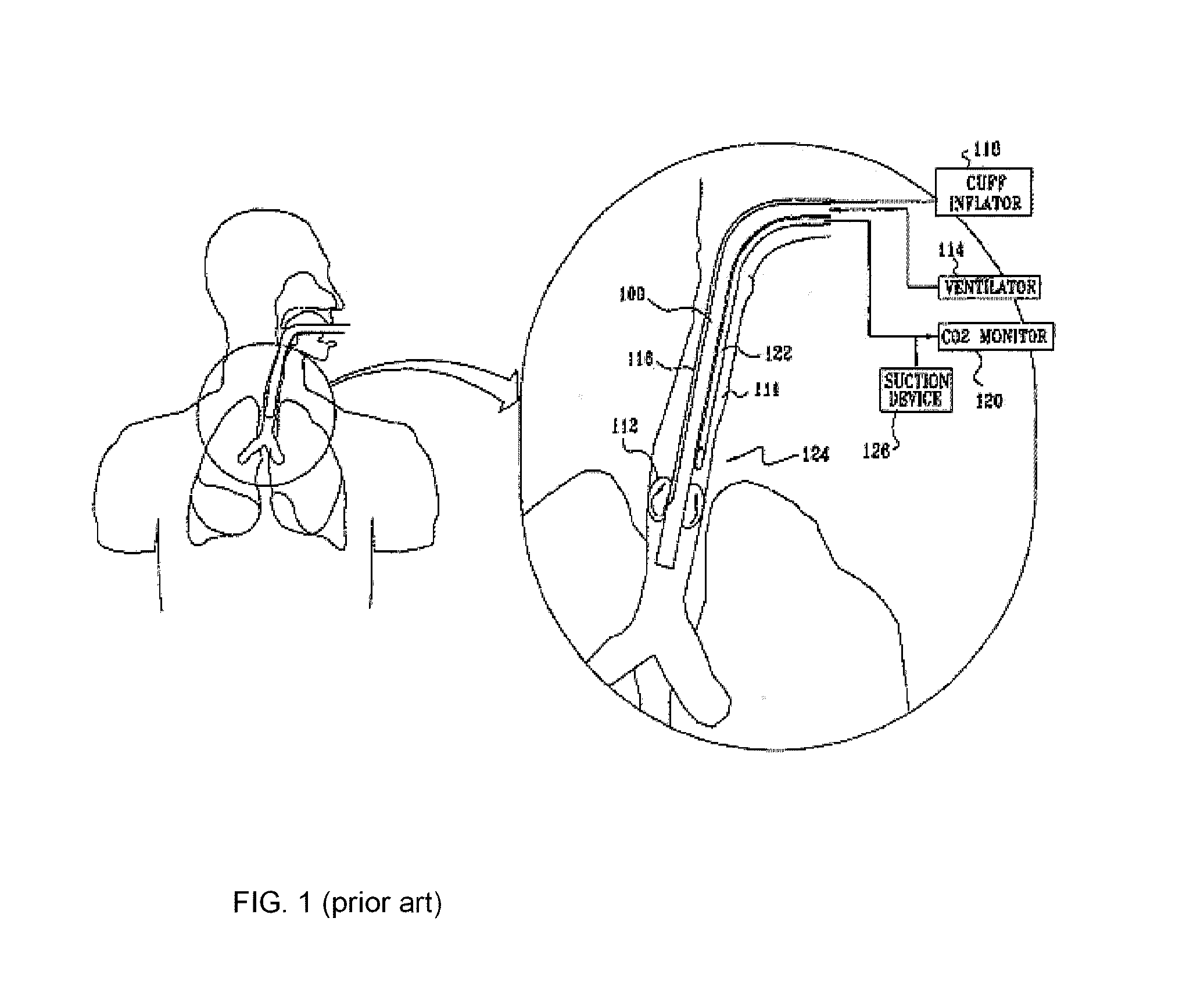
In practice however, due to the finite axial length accommodated by the tape or other fastening means required to attach the cuff sealingly to the main tube of the structure, the opening from the suction line is disposed too far above the upstream ovate surface of the cuff to ensure removal by suction of all the unwanted fluids collecting in that region.
Moreover, the oval shape of the cuff inevitably leads to having the most crucial area of fluid collection, at the contact between the cuff and the trachea surface, being too narrow for the reach of any suction device.
Hence, suction above oval balloons may not ensure complete removal of all secretions.
Yet such sealing pressure cannot be implemented in practice due to the risk of tissue anoxia and other complications: as the cuff pressure exceeds the capillary pressure of the tracheal tissues (which is normally 25 mm of mercury), tissue anoxia occurs, and varying degrees of tracheal injury result.
More dramatic is full thickness erosion, with perforation of the inominate artery anteriorly or posteriorly into the esophagus; both of these events are associated with a high rate of mortality.
Any prolonged pressure above 25 torr increases the risk of tracheal necrosis.

Method used


Image

  • Method and apparatus for protection of trachea during ventilation
  • Method and apparatus for protection of trachea during ventilation
  • Method and apparatus for protection of trachea during ventilation

Examples


Embodiment Construction

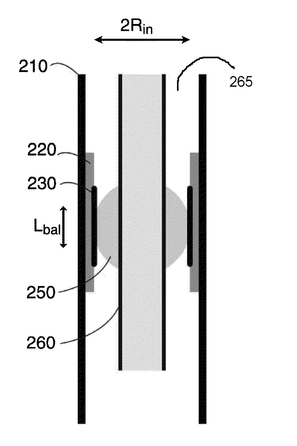
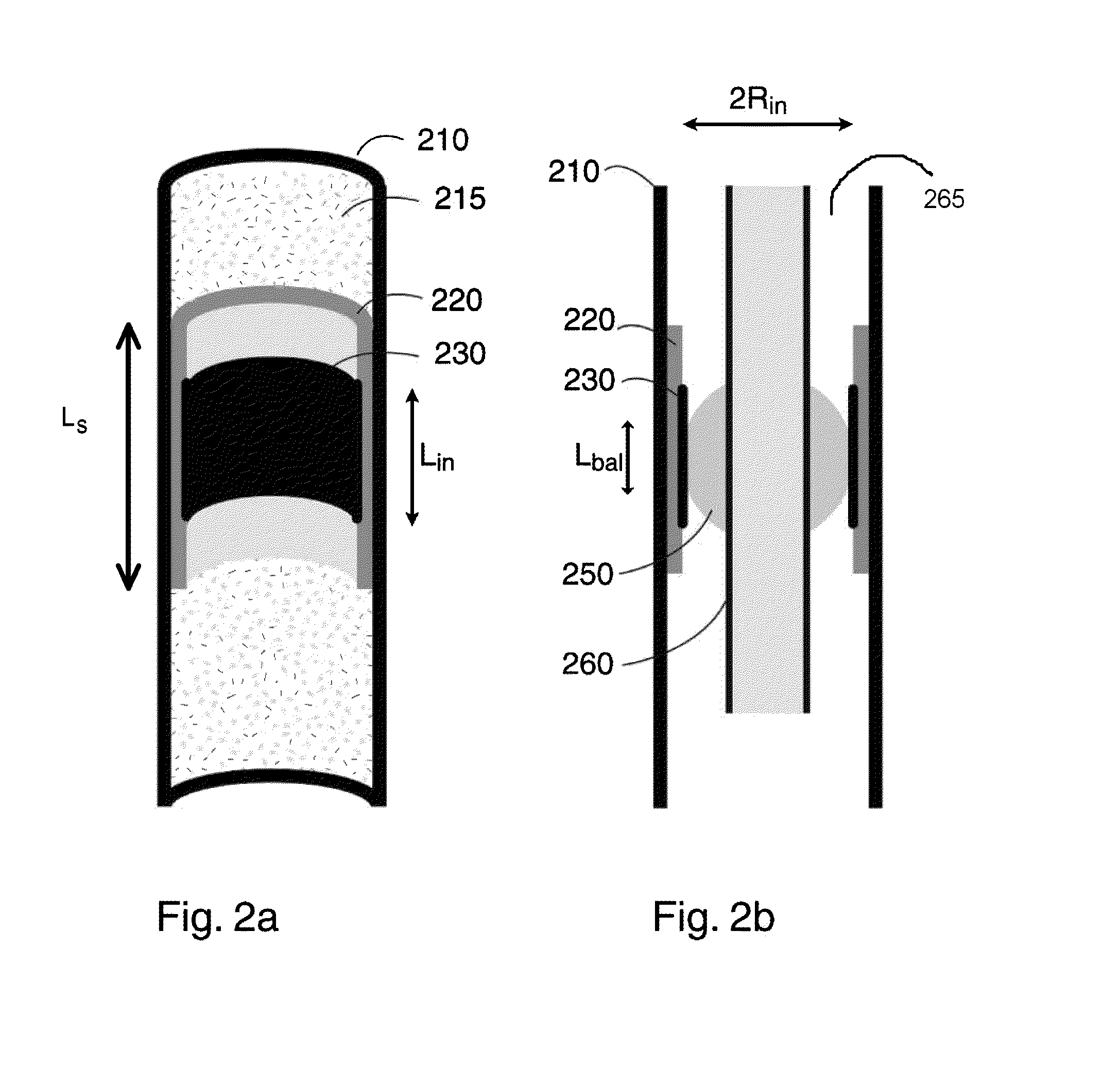
[0074]In accordance with embodiments of the invention, when the ETT is deployed, it is deployed in a such as way that a portion of the ETT contacts a “sleeve” element via a mediating element, thus creating a seal within the sleeve and between the lungs and the oral cavity. FIGS. 2a and 2b show in cut-away perspective and cross-sectional view along the longitudinal axis, respectively, an example of such a sleeve element 220, constructed and operative in accordance with embodiments of the present invention, deployed in a trachea 210. As shown, sleeve element 220 is of quasi-cylindrical shape, and of length Ls. It will also be appreciated that for purposes of the present discussion, sleeve element 220 is an expandable sleeve element in an expanded state; such expandable sleeve elements will be discussed in greater detail below.

[0075]As shown in both FIGS. 2a and 2b, the outer surface of sleeve element 220 is in contact with the tracheal tissue; as shown in FIG. 2b, which in addition to...


PUM

PropertyMeasurementUnit
diameteraaaaaaaaaa
lengthaaaaaaaaaa
lengthaaaaaaaaaa

Abstract

Disclosed are methods for intubating a patient, comprising deploying a tracheal tube, a sleeve and a cuff into a human trachea such that after deployment, the tracheal tube passes through the sleeve within the trachea, the cuff contacts the outer surface of the tracheal tube and the inner surface of the sleeve and spaces the sleeve from the tube, and the outer surface of the sleeve contacts the trachea, so as to provide a seal, in the interstitial area between the wall of the trachea and the tube, between a proximal portion of the human trachea above the cuff and a distal portion of the human trachea below the cuff. Other embodiments are also disclosed.

Description

RELATED APPLICATION INFORMATION[0001]This application is a continuation in part of U.S. Non-Provisional application Ser. No. 12 / 823,114 filed on Jun. 24, 2010 and incorporated herein by reference in it entirety. This application is also a continuation in part of PCT / US2010 / 039881 filed on Jun. 24, 2010 and incorporated herein by reference in it entirety. This application is also a continuation in part of PCT / US2009 / 062227 filed on Oct. 27, 2009 and incorporated herein by reference in it entirety. This application claims priority from U.S. Provisional Application Ser. Nos. 61 / 108,594, filed Oct. 27, 2008 and incorporated herein by reference in it entirety; 61 / 219,769, filed Jun. 24, 2009 and incorporated herein by reference in it entirety; 61 / 236,553, filed Aug. 25, 2009 and incorporated herein by reference in it entirety; 61 / 238,151, filed Aug. 29, 2009 and incorporated herein by reference in it entirety; 61 / 329,106 filed on Apr. 29, 2010 and incorporated herein by reference in it e...

Claims


Application Information

Patent Timeline
Patent Type & Authority Applications(United States)
IPC IPC(8): A61M16/04
CPCA61L29/085A61M16/04A61M16/0434A61M16/0488A61M16/0484A61M2205/0238A61M2209/06A61M16/0445A61M16/0479A61M2205/0205
Inventor ZACHAR, ORON
Owner AIRWAY MEDIX SPOLKA Z O O
Learn More