Large bore auto-fill float equipment

a float equipment and large bore technology, applied in the direction of valve operating means/releasing devices, borehole/well accessories, transportation and packaging, etc., can solve the problems of inability to adjust the activation variables of existing auto-fill systems, large internal flow bores with relatively small diameters, etc., to achieve maximum debris tolerance, increase the flow rate of the auto-fill, and increase the effect of fluid pressur

Active Publication Date: 2011-12-01
FRANKS INT
View PDF19 Cites 30 Cited by
  • Summary
  • Abstract
  • Description
  • Claims
  • Application Information

AI Technical Summary

Benefits of technology

[0016]Fluid pressure can then be increased above said seated ball. At a predetermined, specified pressure, at least one composite pin will shear, thereby allowing said ball seat member to shift downward, away from the valves. This event actuates the mechanism holding the flappers open, thereby allowing said valves to close. As pressure continues to increase above the ball, the collets of the ball seat member spread apart, allowing the ball to pass through said opened collets, and be expelled from the assembly into the wellbore below thereby removing the restriction from the central flow bore of the assembly. The colletted ball seat member permits changing of both the number of composite shear pins (thereby permitting adjustment of the activation pressure) and flow port size (thereby permitting adjustment of the activation flow rate) of the system.
[0017]According to one particularly advantageous embodiment of the present invention, the flapper and valve bodies are manufactured from high-temperature resins compression molded around a carbon- or glass-reinforced framework for added strength. The curved profi...

Problems solved by technology

Without such a float collar, the heavy cement slurry pumped into the annular space around the outside of the casing can U-tube or reverse flow back into the inner bore of the casing, which can result in a very undesirable situation.
Additionally, existing auto-fill systems have limited to no capability to adjust the activation variables such as, for example, deactivation pressure and/or flow rate.
Further, although float assemblies have been known in the art...

Method used


Image

  • Large bore auto-fill float equipment
  • Large bore auto-fill float equipment
  • Large bore auto-fill float equipment

Examples


Embodiment Construction

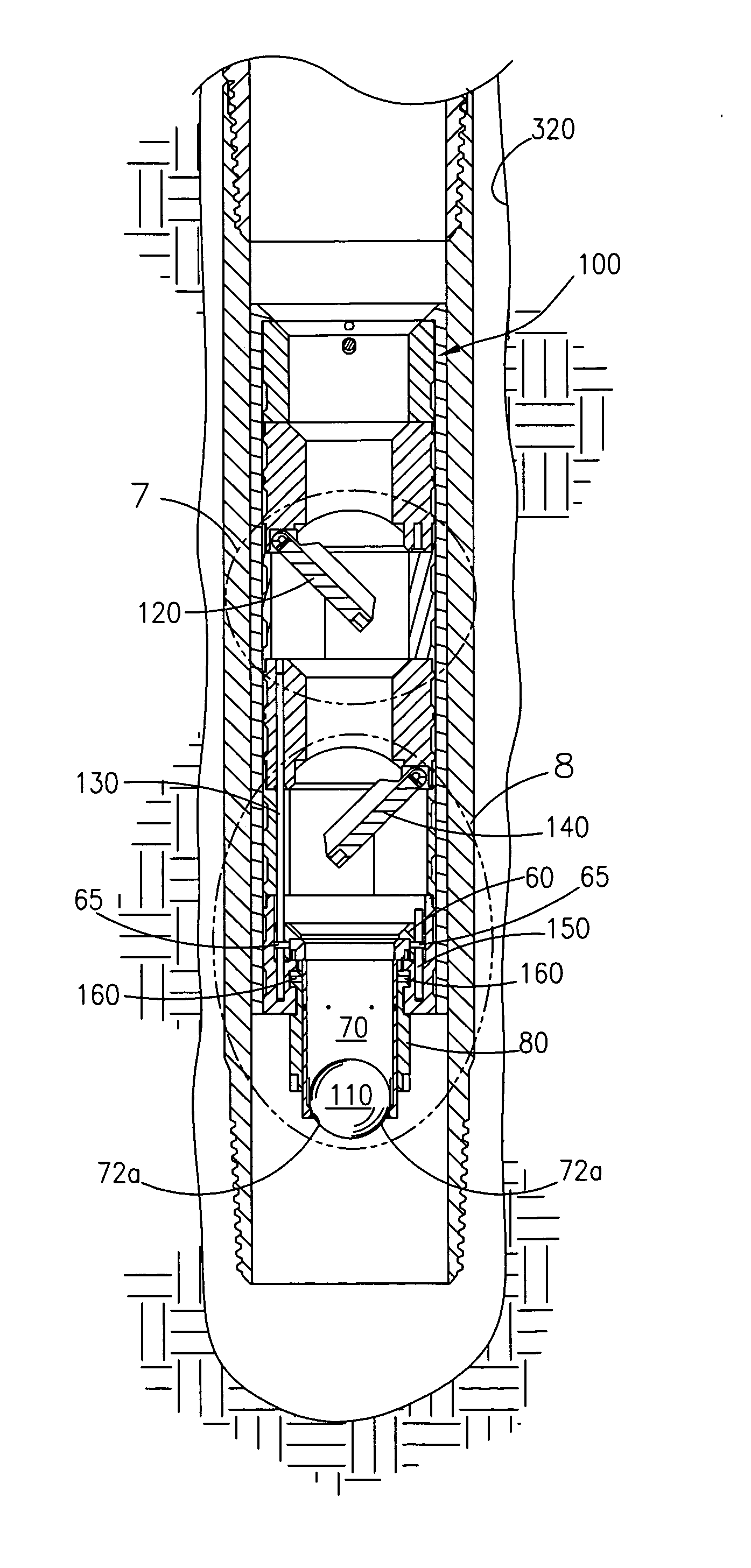
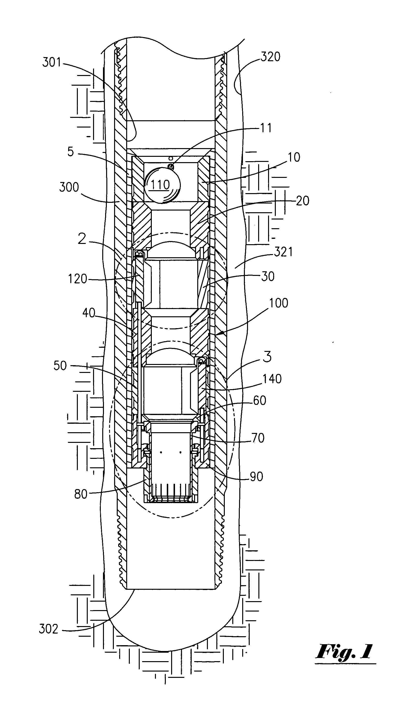
[0041]FIG. 1 depicts a side sectional view of “auto-fill” type float assembly 100 of the present invention installed within a wellbore 320 which extends into the earth's crust. As depicted in FIG. 1, float assembly 100 is installed near the bottom (distal) end 302 of casing string 300 which has a central flow bore 301. Generally, float assembly 100 of the present invention permits cement slurry to flow down central flow bore 301 and out the open distal end 302 of casing 300 and into annular space 321 formed between wellbore 320 and the external surface of casing 300. Float assembly 100 permits cement slurry to flow out of distal end 302 of casing 300, while preventing back-flow of such heavy cement slurry into central flow bore 301 of casing 300 when pumping ceases. Without float assembly 100, relatively heavy cement slurry pumped into annular space 321 can “U-tube” or reverse flow back into central flow bore 301 of casing 300.

[0042]As set forth in greater detail below, float assemb...


PUM


Abstract

An auto-fill type float collar assembly is provided. The float collar assembly of the present invention has at least one curved flapper-style valve, preferably constructed of composite, non-metallic material. Each flapper of the present invention has a substantially 90° range of motion, and is closed via a torsion spring. Each flapper is held in the open (or “auto-fill”), position via an external shifting mechanism passing around, rather than through, the central flow bore of the assembly. A floatable actuation ball can be run with the tool, or pumped downhole, in order to selectively actuate the assembly and close the flappers when desired.

Description

CROSS REFERENCES TO RELATED APPLICATION[0001]Priority of U.S. provisional patent application Ser. No. 61 / 347,615 filed May 24, 2010, incorporated herein by reference, is hereby claimed.STATEMENTS AS TO THE RIGHTS TO THE INVENTION MADE UNDER FEDERALLY SPONSORED RESEARCH AND DEVELOPMENT[0002]NoneBACKGROUND OF THE INVENTION[0003]1. Field of the Invention[0004]The present invention pertains to a large bore float assembly. More particularly, the present invention pertains to a large bore float assembly having at least one flapper valve. More particularly still, the present invention pertains to a float assembly having non-metallic valves and other components, yet providing a greater pressure rating than conventional float assemblies.[0005]2. Brief Description of the Prior Art[0006]Drilling of an oil or gas well is frequently accomplished using a surface drilling rig and tubular drill pipe. When installing drill pipe (or other tubular goods) into a well, such pipe is typically inserted in...

Claims


Application Information

Patent Timeline
IPC IPC(8): F16K31/18
CPCE21B2034/005E21B21/10Y10T137/7846Y10T137/7426Y10T137/1662Y10T137/7854Y10T137/1677Y10T137/87981E21B2200/05E21B2200/04E21B34/16
Inventor GROESBECK, BRADARCEMENT, JEFFREYJORDAN, JOHN C.MARTENS, JAMES G.
Owner FRANKS INT
Why Eureka
Try Eureka