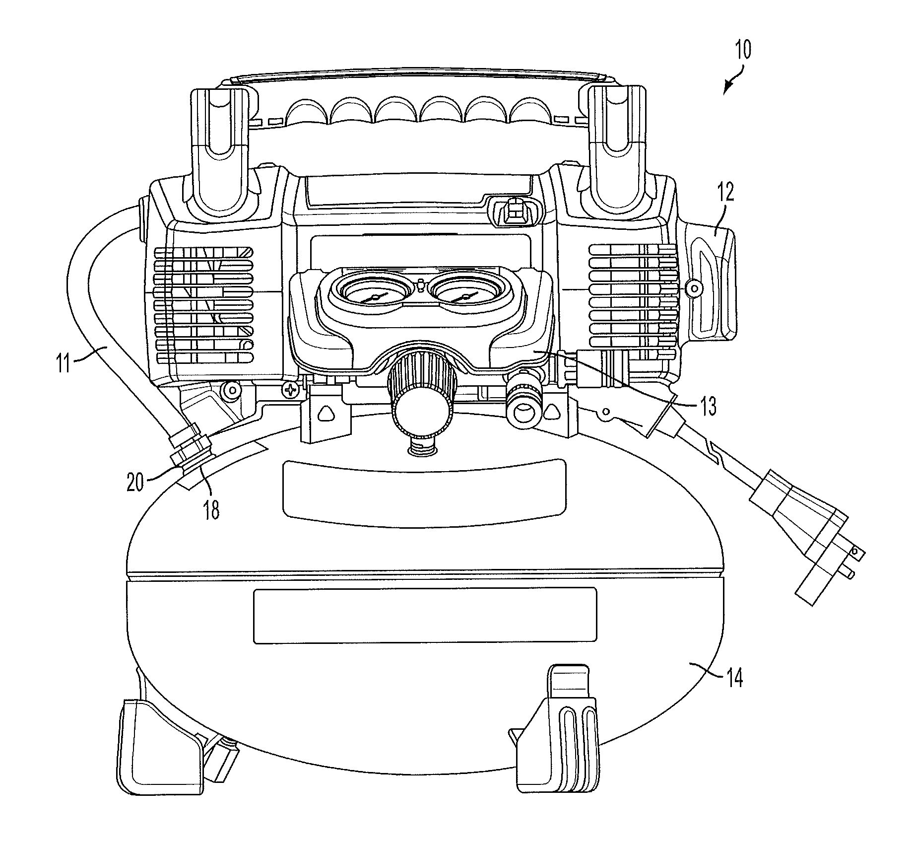
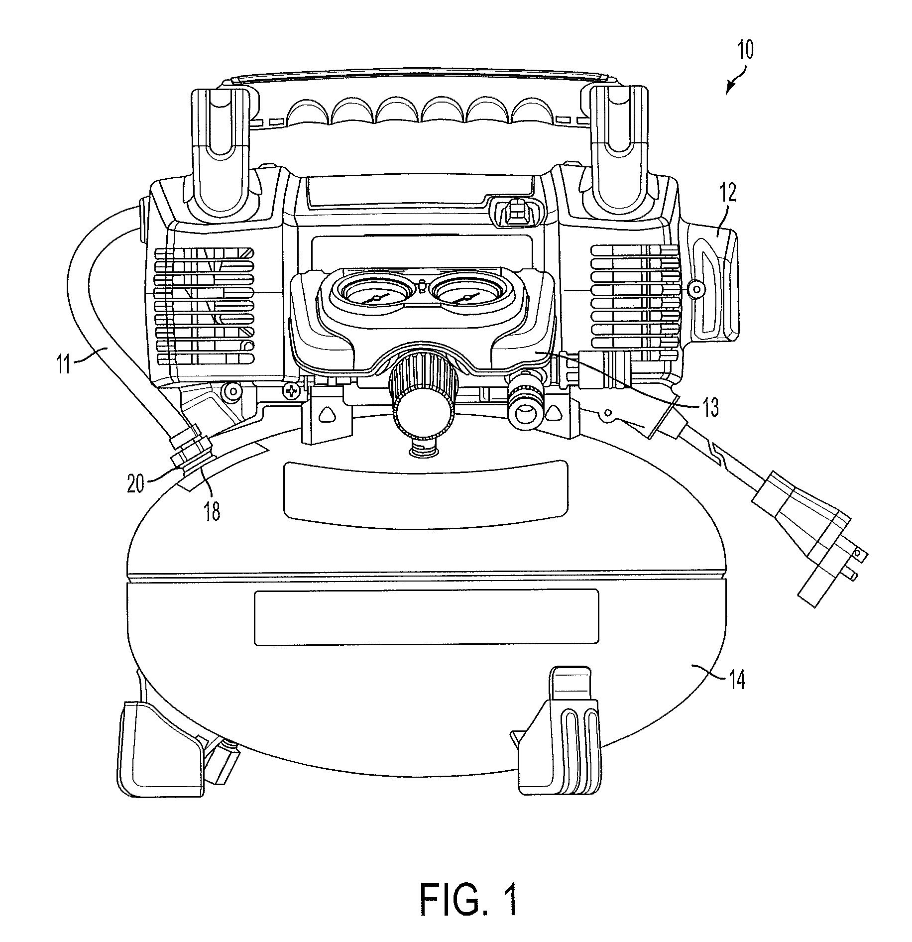
Compressible Fluid Discharge Muffler
a compressor and fluid discharge technology, applied in the direction of positive displacement liquid engine, piston pump, separation process, etc., can solve the problems of affecting the efficiency of the compressor, and affecting the operation comfort of the compressor, so as to reduce the noise and vibration of the air storage tank, and reduce the noise of compressed fluid
- Summary
- Abstract
- Description
- Claims
- Application Information
AI Technical Summary
Benefits of technology
Problems solved by technology
Method used
Image
Examples
second embodiment
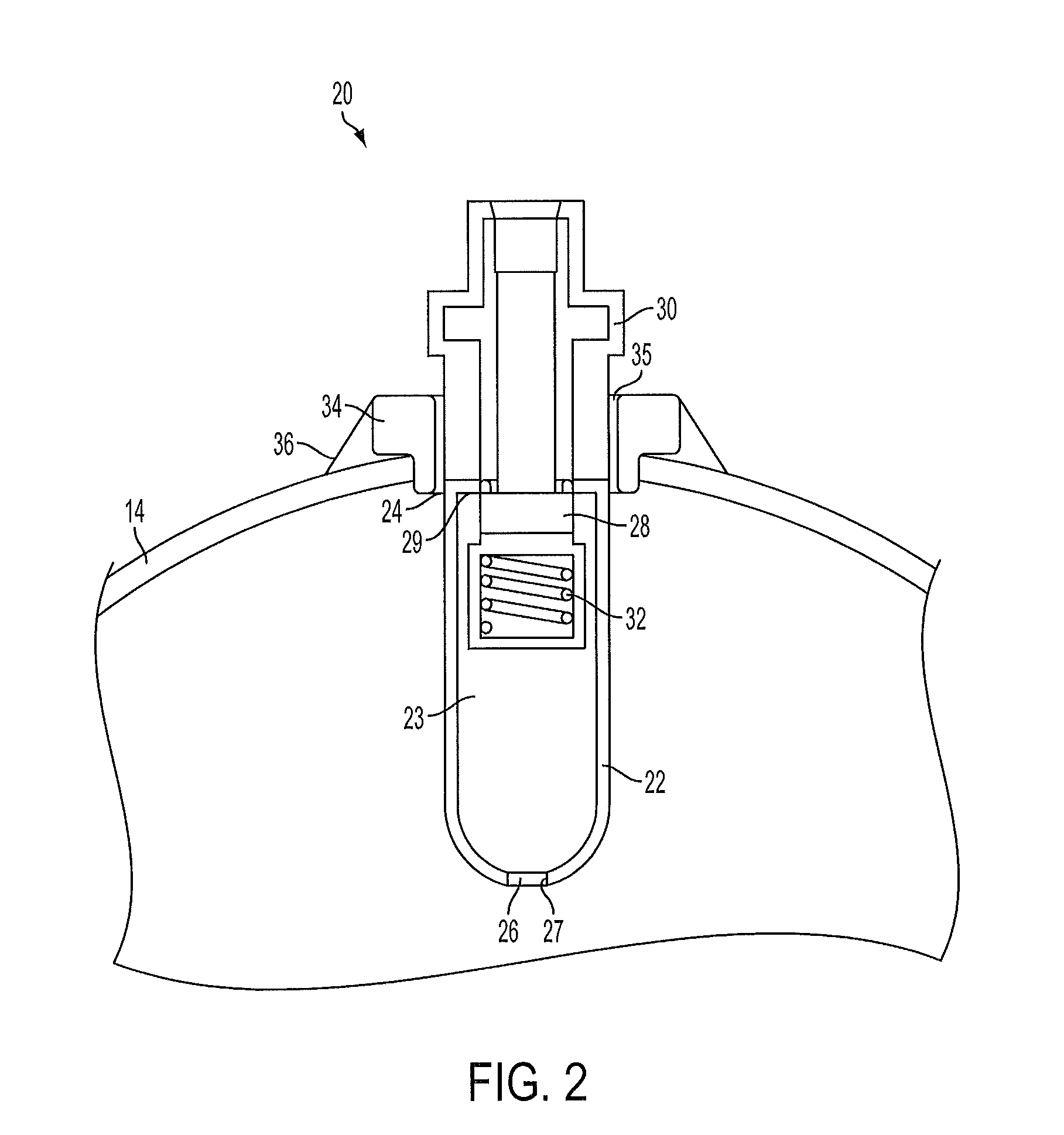
[0038]In the present invention, shown in FIG. 3, the muffler 40 can be welded directly to the air storage tank 14. The muffler 40 includes a tubular body 42 having an inlet 44 at a first end and an outlet 46 at a second end opposing the first end. The inlet 44 has a greater diameter than the outlet 46. The muffler 40 is integrally connected to the air storage tank 14. For example, as shown in FIG. 3, the tubular body 42 is welded with weld bead 56 at the intake port 18 on an inner wall of the air storage tank 14. The outlet 46 of muffler 40 restricts the flow of air being delivered from the compressor 12 to the air storage tank 14.
[0039]Alternatively, the upper outer surface of the muffler can be a threaded surface that is threaded onto an inner threaded surface of the weld flange. Also, the upper inner surface of the muffler can be a threaded surface that is threaded onto an outer threaded surface of the weld flange 34.
[0040]As shown in FIG. 3, the outlet 46 in the second end of th...
fourth embodiment
[0047]In FIG. 9, the muffler 920 serves as the air discharge tube for pressurized air being delivered from the compressor 912 to the air storage tank 914. The muffler cavity 923 extends from the compressor to the check valve 930 serving as the restricting member. Pressurized air is discharged from the muffler / check valve combination through the outlet 926 and enters the air storage tank 914.
[0048]More than one muffler of the present invention can be used in series along the path between the compressor and the air storage tank.
[0049]The muffler can also protect the check valve from corrosion caused by condensate in the air storage tank. Tilting of the compressor, for example, during movement from one location to another location, could allow water or other condensate to enter into air compressor. The check valve serves to check the flow of fluid from the air storage tank to the compressor. However, if the check valve comes in contact with water or other liquid condensate, over time, ...
PUM
| Property | Measurement | Unit |
|---|---|---|
| Fraction | aaaaa | aaaaa |
| Diameter | aaaaa | aaaaa |
Abstract
Description
Claims
Application Information
 - R&D
- Intellectual Property
- Life Sciences
- Materials
- Tech Scout
- Unparalleled Data Quality
- Higher Quality Content
- 60% Fewer Hallucinations
Browse by: Latest US Patents, China's latest patents, Technical Efficacy Thesaurus, Application Domain, Technology Topic, Popular Technical Reports.
© 2025 PatSnap. All rights reserved.Legal|Privacy policy|Modern Slavery Act Transparency Statement|Sitemap|About US| Contact US: help@patsnap.com


