Optoelectronic oscillator using a high finesse etalon

a technology of optoelectronic oscillators and etalons, applied in non-linear optics, instruments, optics, etc., can solve the problems of increasing phase noise, affecting the stability of rf filters, and costing to make ultra-narrow bandwidth rf filters, so as to achieve less phase noise, lower phase noise, and higher rf frequency stability

Active Publication Date: 2011-12-01
UNIV OF CENT FLORIDA RES FOUND INC
View PDF2 Cites 27 Cited by
  • Summary
  • Abstract
  • Description
  • Claims
  • Application Information

AI Technical Summary

Benefits of technology

[0008]Most OED's employ an RF Filter as the mode selector for signal generation. See for instance, [11] and U.S. Pat. No. 5,777,778. In this invention, a F-P interferometer, or etalon, is used in replacement of the RF Filter. In one embodiment, a 10.287 GHz optoelectronic oscillator is demonstrated which uses a 1000 finesse Fabry-Perot etalon as the mode selector instead of an RF filter. The results are compared with a standard optoelectronic loop with an RF filter. The substitution of the RF filter with the optical filter results in a higher RF frequency stability and lower phase noise.
[0009]We describe an optoelectronic loop design which uses a high finesse Fabry-Perot etalon as the mode selector instead of an RF filter. The inclusion of the Fabry-Perot etalon instead of the RF filter results in less phase noise, due to the higher Q, and also results in higher RF frequency stability due to the ultralow temperature dependency of the Fabry-Perot etalon. The results of the OEO with a Fabry-Perot etalon are compared to the conventional OEO with the RF filter. When the same laser source, intensity modulator, optical delay length and RF amplifier are used, the OEO with the Fabry-Perot etalon results in lower phase noise and higher RF frequency stability.

Problems solved by technology

There are some drawbacks of the standard OEO: a high gain RF amplifier is needed in order to compensate the losses in the RF loop, and it is costly to make an ultra narrow bandwidth RF filter which is required when the optical delay line is long.
Moreover, the additional loss from the RF filter decreases the cavity Q of the optoelectronic oscillator which results in an increase in the phase noise.
Another drawback of the RF filter is the temperature dependency; small fluctuations of the temperature result in fluctuations at the peak position of the resonance, and hence the phase from the RF filter changes.

Method used


Image

  • Optoelectronic oscillator using a high finesse etalon
  • Optoelectronic oscillator using a high finesse etalon
  • Optoelectronic oscillator using a high finesse etalon

Examples


example

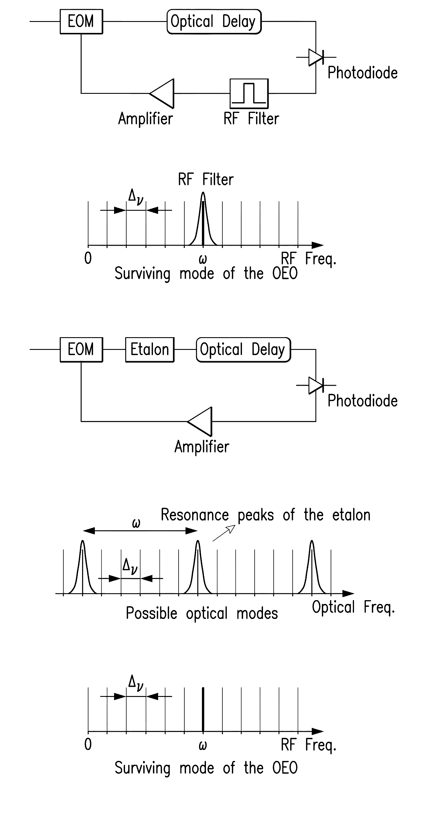
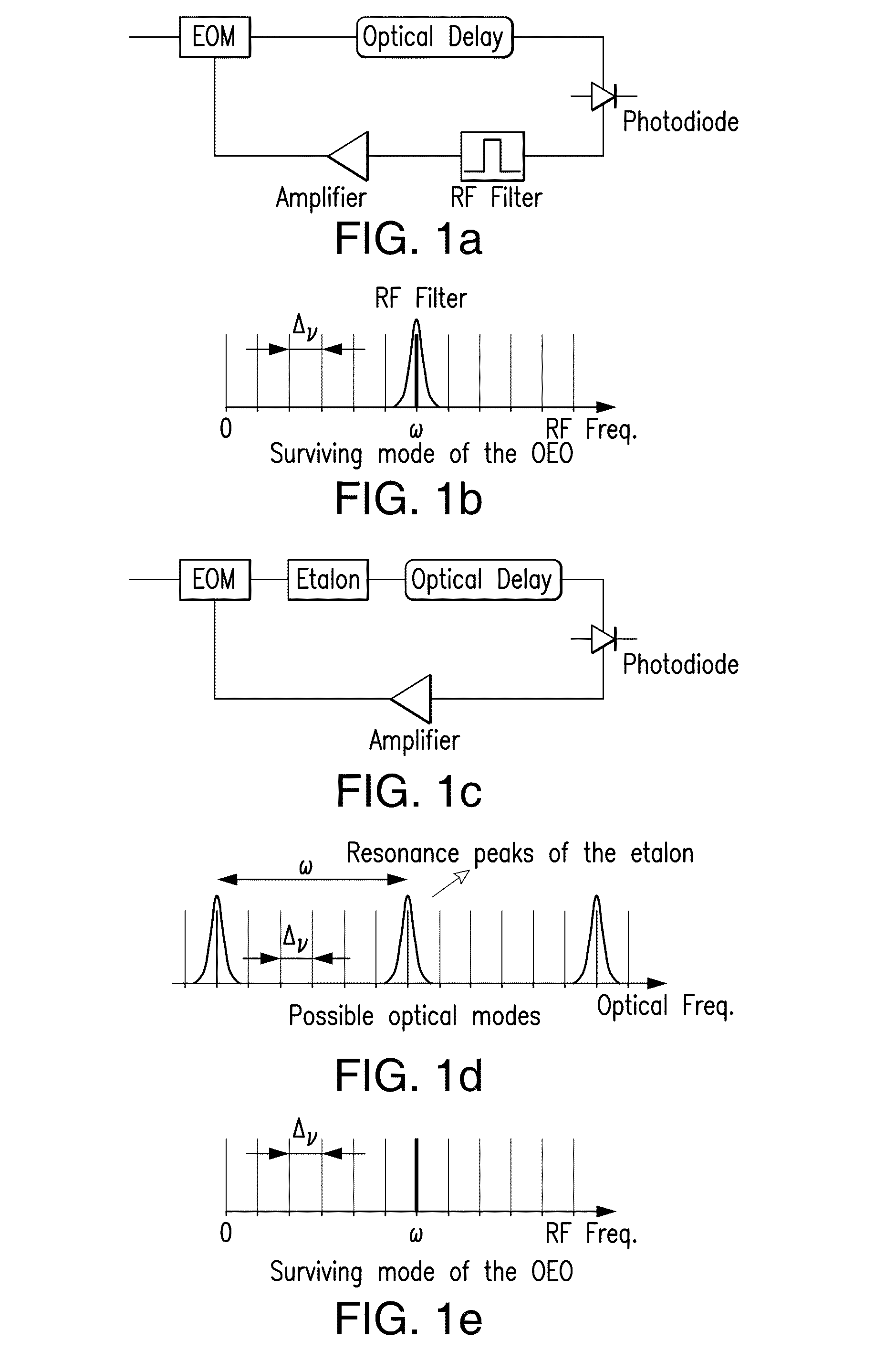
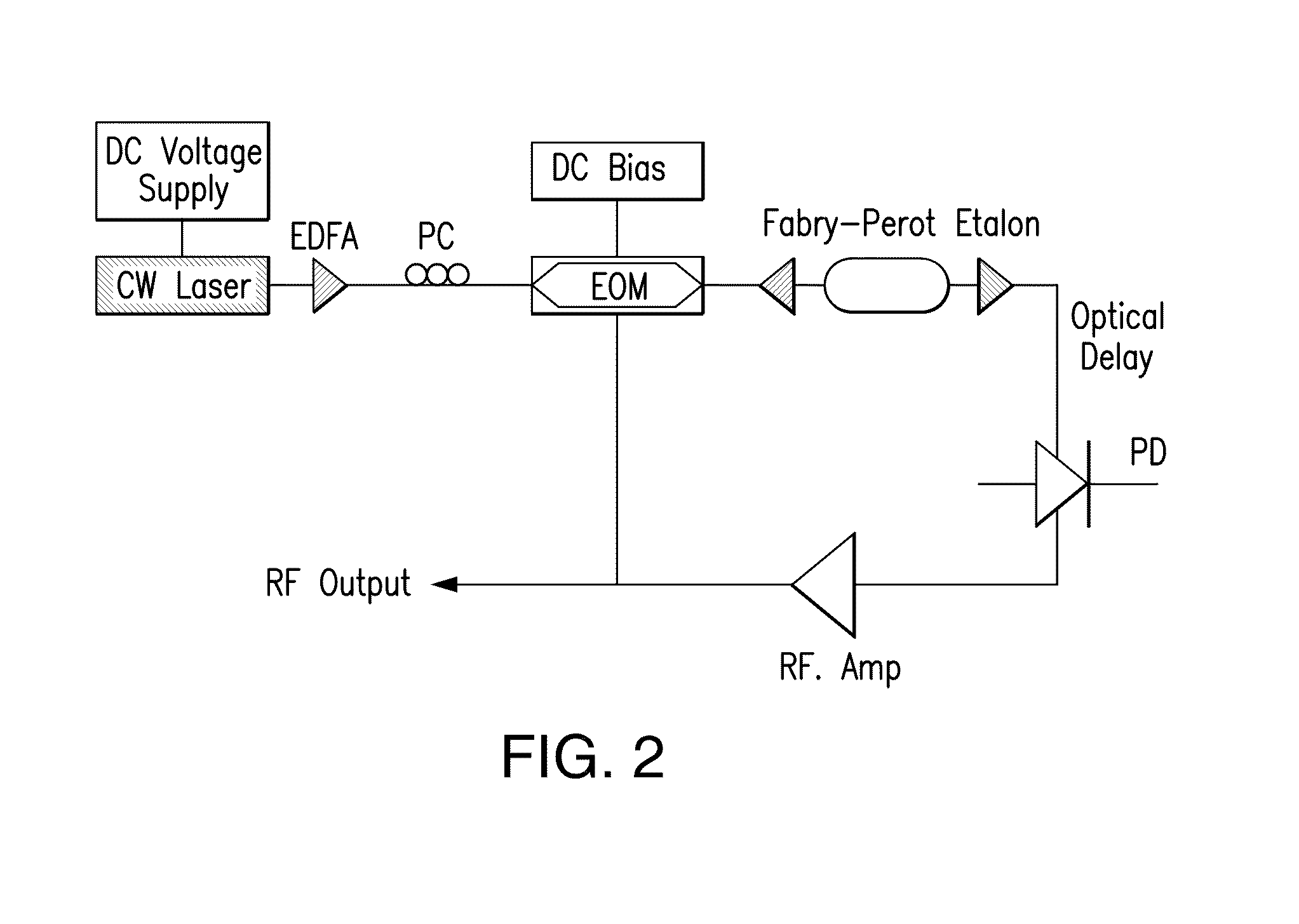
[0018]The schematic of the OEO with the Fabry-Perot etalon is shown in FIG. 2. A 1550 nm CW laser is used as the light source. The optical frequency of the CW laser is tunable by applying an external voltage. The output of the CW laser is amplified and sent to the electro-optic modulator (EOM) which is biased at quadrature. A 1000 finesse Fabry-Perot etalon with 10.287 GHz free spectral range (FSR) is used as the mode selector, as described. The etalon's stability is advantageous as it becomes the primary frequency reference in the OEO. The etalon is made of ultralow expansion quartz and is sealed, so it is less susceptible to environmental changes, such as temperature or air pressure. The full width half maximum (FWHM) of the resonance of the etalon is 10 MHz. The fiber to fiber insertion loss of the etalon is only 1 dB. A total optical delay of ten (10) meters is employed in order to get sufficient electrical supermode suppression. The photodiode has 16 GHz bandwidth with 0.8 A / W ...


PUM

PropertyMeasurementUnit
insertion lossaaaaaaaaaa

Abstract

An optoelectronic oscillator (OEO) is used to provide a continuous, high Q, modulated signal for a variety of purposes, including a carrier wave for communications, and radar emissions. The OEO of this invention replaces an RF filter in the conventional OEO with an interferometer, preferably a high finesse Fabry-Perot etalon as the mode selector, providing lower phase noise and higher RF frequency stability.

Description

PRIORITY DATA AND INCORPORATION BY REFERENCE[0001]This application claims benefit of priority to U.S. Provisional Patent Application No. 61 / 349,427 filed May 28, 2010 which is incorporated by reference in its entirety.[0002]This work was supported by the Defense Advanced Research Programs Agency under the PHOBIAC program and National Science Foundation under contract DMR 0120967. The United States Government may enjoy certain rights in the invention(s) claimed herein.BACKGROUND OF THE INVENTION[0003]1. Field of the Invention[0004]The present invention relates to optoelectronic oscillators of improved performance providing high RF frequency stability and reduced noise. These find application in a wide variety of fields, wherever signal generation is required at high respective frequencies with reduced noise, such as radar.[0005]2. Background of the Invention[0006]Microwave generators with multi gigahertz frequency, high spectral purity and high RF frequency stability have application...

Claims


Application Information

Patent Timeline
Patent Type & Authority Applications(United States)
IPC IPC(8): G02F1/03
CPCG02F2001/212G02F1/0121G02F1/212
Inventor DELFYETT, PETER J.OZDUR, IBRAHIM T.
Owner UNIV OF CENT FLORIDA RES FOUND INC
Why Eureka
Try Eureka