Surface Ship, Deck-Launched Anti-Torpedo Projectile

a deck-launched anti-torpedo and surface ship technology, applied in the direction of projectiles, weapons, marine torpedoes, etc., can solve the problems that no deck-launched anti-torpedo has been able to meet all the above-mentioned requirements, and the shkval is potentially a very significant offensive threat, etc., to achieve greater height, reduce the aft portion of the body, and increase the “span”

Inactive Publication Date: 2011-12-08
LOCKHEED MARTIN CORP
View PDF5 Cites 23 Cited by
  • Summary
  • Abstract
  • Description
  • Claims
  • Application Information

AI Technical Summary

Benefits of technology

[0018]In some embodiments, the diameter of the aft portion of the body is reduced. This enables the use of tail fins with a greater height (i.e., a greater tail fin “span”) while still remaining within the cavity.

Problems solved by technology

Notwithstanding its defense-motivated origins, the Shkval is potentially a very significant offensive threat.
To date, no deck-launched anti-torpedo has been able to fulfill all of the above-mentioned requirements.

Method used


Image

  • Surface Ship, Deck-Launched Anti-Torpedo Projectile
  • Surface Ship, Deck-Launched Anti-Torpedo Projectile
  • Surface Ship, Deck-Launched Anti-Torpedo Projectile

Examples


first embodiment

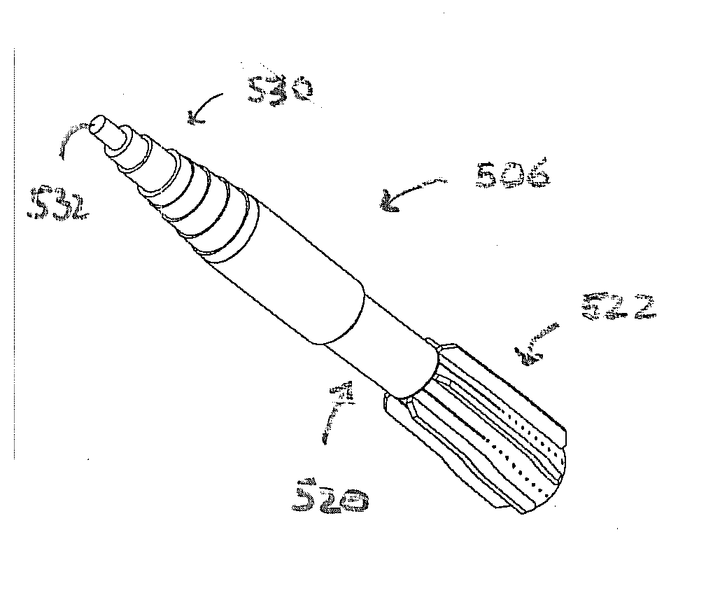
[0052]Turning now to FIGS. 5 through 8, an anti-torpedo projectile in accordance with the illustrative embodiment of the present invention. As depicted in these Figures, in particular FIG. 5, projectile 506 comprises a plurality of substantially right-circular cylindrical sections 530 that make up the nose section. Tip 532 of the nose is flat, as is required to create the cavitation phenomena. The gradual increase in diameter of the cylindrical sections defines a geometry that remains completely within the bounds of the cavity formed by the blunt nose face. It also prevents the projectile from pitching down (i.e., overturning) during water entry. The aft section of projectile 506 includes region 520, which has a reduced diameter relative to the forward portion of the projectile's body. This enables an increase in the fin span of fins 522.

[0053]FIG. 6 depicts a side view of projectile 506 and shows the diameters of the various cylindrical sections, as well as the chord length of the ...

second embodiment

[0054]FIGS. 9 through 12 depict an anti-torpedo projectile in accordance with the illustrative embodiment of the present invention. As depicted in these Figures, in particular FIG. 9, the nose of projectile 906 comprises only three cylindrical sections 930. Unlike projectile 506, the aft section of projectile 906 is not reduced in diameter. As a consequence, fins 922 have a relatively shorter span than could otherwise be the case.

[0055]FIG. 10 is a side view that depicts various dimensions of projectile 906. FIG. 11 is a cross section along the line A-A of FIG. 10 in the direction shown. FIG. 12 depicts a tail end view of projectile 906 and shows some additional dimensions pertinent to fins 922.

third embodiment

[0056]FIGS. 13 through 16 depict an anti-torpedo projectile in accordance with the illustrative embodiment of the present invention. As depicted in these Figures, in particular FIG. 13, projectile 1306 comprises a nose having two cylindrical sections 1330 and body portion 1340 that is shaped as a right circular cone. Body portion 1340 comprises a taper angle that is less than the minimum intended water entry angle, in this case 3.5 degrees. Like projectile 906, the aft portion of the body is not reduced in diameter. Projectile 1306 includes a plurality of fins 1322.

[0057]FIG. 14 is a side view that depicts various dimensions of projectile 1306. FIG. 15 is a cross section along the line A-A of FIG. 14 in the direction shown. FIG. 15 depicts the multi-piece construction of projectile 1306. In some embodiments, the forward section will be formed of a relatively denser material to site the center of gravity of projectile 1306 relatively forward. FIG. 16 depicts a tail end view of projec...


PUM


Abstract

A surface ship, deck-launched anti-torpedo projectile is disclosed. The projectile has a blunt-end nose to create a cavitating running mode. The nose has a gradual, stepped, right-circular cylindrical or conic geometry. In some embodiments, the projectile includes a plurality of tail fins that are dimensioned and arranged to be within the generalized elliptical cavity that shrouds the projectile in the cavitating running mode.

Description

CROSS REFERENCE TO RELATED APPLICATIONS[0001]This case claims priority of U.S. Provisional Patent Application Ser. No. 60 / 908,369, which was filed on Mar. 27, 2007 and is incorporated by reference herein.FIELD OF THE INVENTION[0002]The present invention relates to a defense against high-speed torpedoes.BACKGROUND OF THE INVENTION[0003]The Shkval is a high-speed, supercavitating, rocket-propelled torpedo developed by Russia. It was designed to be a rapid-reaction defense against U.S. submarines undetected by sonar. It can also be used as a countermeasure to an incoming torpedo, forcing the hostile projectile to abruptly change course and possibly break its guidance wires.[0004]The solid-rocket propelled torpedo achieves a high velocity of 250 knots (288 mph) by producing an envelope of supercavitating bubbles from its nose and skin, which coat the entire weapon surface in a thin layer of gas. This causes the metal skin of the weapon to avoid contact with the water, significantly redu...

Claims


Application Information

Patent Timeline
Patent Type & Authority Applications(United States)
IPC IPC(8): F42B15/22F42B10/02
CPCF42B15/22F42B10/06F42B10/46
Inventor FU, JYUN-HORNGBENEDICT, LANCE HAMILTONPAULIC, ANTONIOKRASS, ROBERT M.
Owner LOCKHEED MARTIN CORP
Why Eureka
Try Eureka