
Contactless communication medium, antenna pattern arrangement medium, communication apparatus, and communication method

Active Publication Date: 2011-12-08
SONY CORP
View PDF16 Cites 6 Cited by
  • Summary
  • Abstract
  • Description
  • Claims
  • Application Information

AI Technical Summary

Benefits of technology

[0025]While some cellular phone terminals incorporate a contactless IC card that provides an electronic money function or the like, there are a large number of cellular phone terminals and portable music players that do not have an electronic money function, and there is a great desire to add an electronic money function to such cellular phone terminals and portable music players. Therefore, in order to conveniently provide an IC card function to the cellular phone terminals, casings that are capable of storing an IC card and that match the housing of a terminal are currently commercially available. With such casings, however, the IC card is merely placed in close proximity to the cellular phone terminal, which may increase the thickness and the volume of the terminal to deteriorate the usability for users. In addition, the contactless IC cards themselves are designed and manufactured on the assumption of use in a free space (an environment in which there is no metal or the like in proximity), and therefore the presence of any housing for a cellular phone terminal or the like that contains metal in proximity may significantly reduce the communication distance.
[0027]In view of the foregoing, it is desirable to eliminate a communication dead zone in communication performed between a contactless communication medium and a reader / writer.
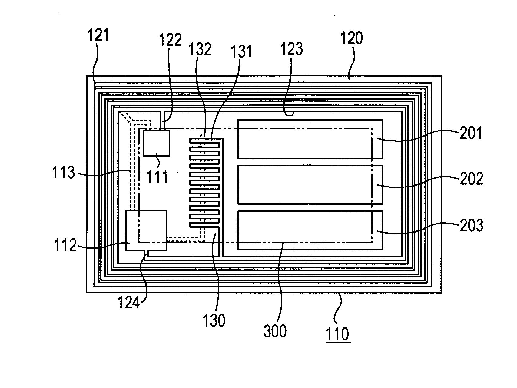
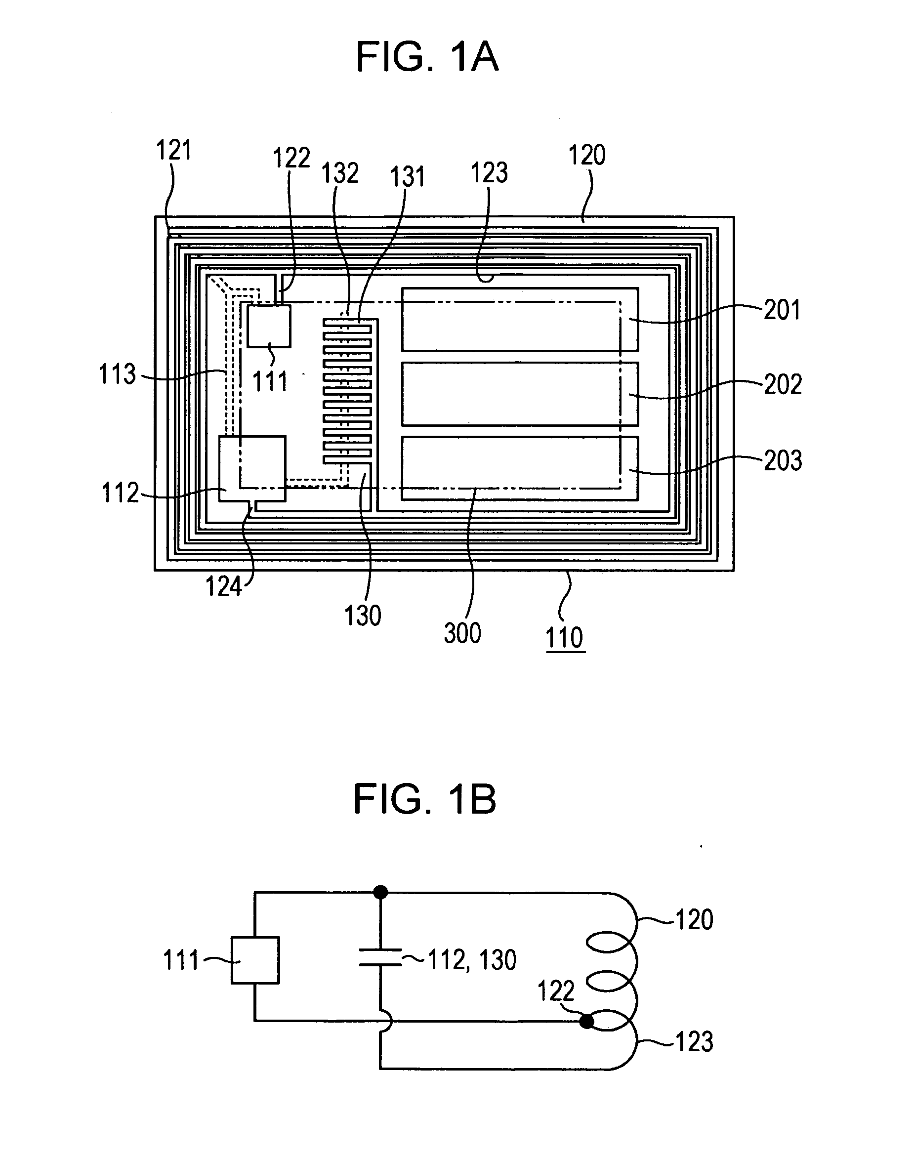
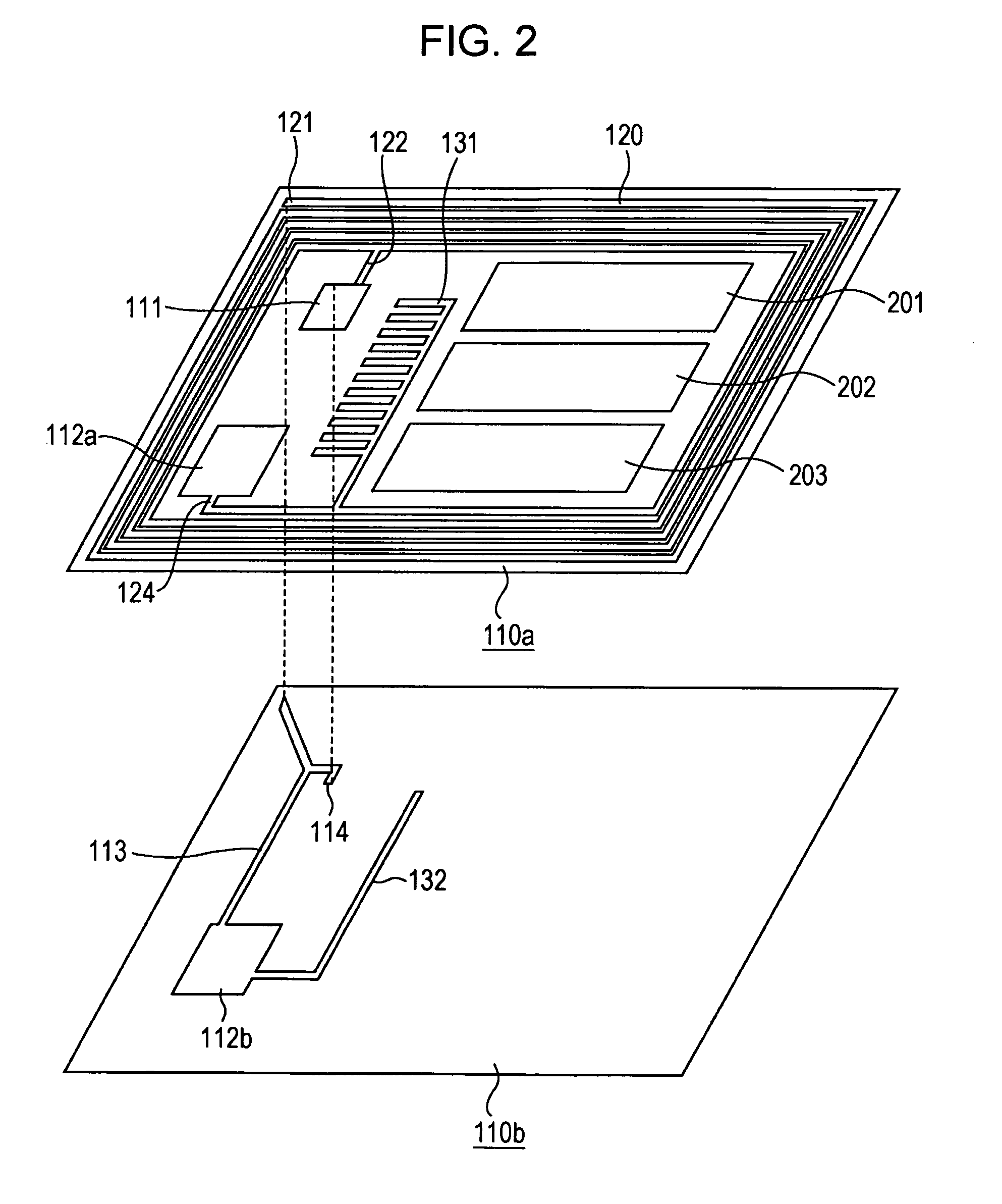
[0030]With the metal pattern, which has a predetermined area and which is not electrically connected to the antenna coil portion or the capacitor, disposed in a region surrounded by the antenna coil portion, it is possible to eliminate a communication dead zone without changing the maximum distance over which communication with a reader / writer may be made.
[0031]According to the present invention, with the metal pattern disposed in a region surrounded by the antenna coil portion, it is possible to eliminate a communication dead zone without changing the maximum distance over which communication with a reader / writer may be made. This allows to favorably perform contactless wireless communication with the reader / writer in the case where the contactless communication medium is affixed to the housing of an electronic device, for example.

Problems solved by technology

With such casings, however, the IC card is merely placed in close proximity to the cellular phone terminal, which may increase the thickness and the volume of the terminal to deteriorate the usability for users.
In addition, the contactless IC cards themselves are designed and manufactured on the assumption of use in a free space (an environment in which there is no metal or the like in proximity), and therefore the presence of any housing for a cellular phone terminal or the like that contains metal in proximity may significantly reduce the communication distance.

Method used


Image

  • Contactless communication medium, antenna pattern arrangement medium, communication apparatus, and communication method
  • Contactless communication medium, antenna pattern arrangement medium, communication apparatus, and communication method
  • Contactless communication medium, antenna pattern arrangement medium, communication apparatus, and communication method

Examples


first modification

4. First Modification

[0088]FIG. 6 shows a first modification of the embodiment. In FIG. 6, components corresponding to those in FIGS. 1A and 2 are denoted by the same reference numerals.

[0089]In the modification of FIG. 6, a single metal pattern with a large area is disposed on the base material on which the antenna coil portion 120 is disposed to serve as a metal pattern 211.

[0090]That is, the single metal pattern 211 is disposed on the front surface of the base material inside the innermost turn of the antenna coil portion 120 and in a region other than regions in which the IC chip 111, the capacitor 112, and the adjustment capacitor 130 are disposed to occupy as large an area as possible.

[0091]In the modification of FIG. 6, the area of the single metal pattern 211 is substantially the same as the total of the areas of the three metal patterns 201 to 203 in the embodiment of FIG. 1A.

[0092]Although not shown, the wireless communication characteristics according to the modification ...

second modification

5. Second Modification

[0093]FIG. 7 shows a second modification of the embodiment. In FIG. 7, components corresponding to those in FIGS. 1A and 2 are denoted by the same reference numerals.

[0094]In the modification of FIG. 7, seven metal patterns divided in the vertical direction are disposed on the base material on which the antenna coil portion 120 is disposed to serve as metal patterns 221 to 227.

[0095]That is, the seven metal patterns 221, 222, 223, . . . , and 227 divided in the vertical direction in case of a horizontally long card are disposed on the front surface of the base material inside the innermost turn of the antenna coil portion 120 and in a region other than regions in which the IC chip 111, the capacitor 112, and the adjustment capacitor 130 are disposed.

[0096]In the modification of FIG. 7, the total of the areas of the seven metal patterns 221 to 227 is substantially the same as the total of the areas of the three metal patterns 201 to 203 in the embodiment of FIG....

third modification

6. Third Modification

[0104]FIG. 9 shows a third modification of the embodiment. In FIG. 9, components corresponding to those in FIGS. 1A and 2 are denoted by the same reference numerals.

[0105]In the modification of FIG. 9, four metal patterns 231 to 234 divided in the vertical direction and four metal patterns 235 to 238 divided in the horizontal direction are disposed on the base material on which the antenna coil portion 120 is disposed to serve as metal patterns 231 to 238.

[0106]That is, the four metal patterns 231, 232, 233, and 234 divided in the vertical direction in case of a horizontally long card are disposed on the front surface of the base material inside the innermost turn of the antenna coil portion 120 and in a region other than regions in which the IC chip 111, the capacitor 112, and the adjustment capacitor 130 are disposed. A space is provided between the metal pattern 232 and the metal pattern 233. Then, the four metal patterns 235, 236, 237, and 238 divided in the...


PUM


Abstract

A contactless communication medium includes: a base material made of an insulating material; an antenna coil portion formed by winding a conductor in a plane on the base material; a capacitor connected to the antenna coil portion; a communication processing section connected to the antenna coil portion and the capacitor to perform a contactless communication process; and a metal pattern having a predetermined area and disposed in a region surrounded by the antenna coil portion, the metal pattern being not electrically connected to the antenna coil portion or the capacitor.

Description

CROSS-REFERENCE TO RELATED APPLICATION[0001]The present application claims priority from Japanese Patent Application No. JP 2010-108803 filed in the Japanese Patent Office on May 10, 2010, the entire content of which is incorporated herein by reference.BACKGROUND OF THE INVENTION[0002]1. Field of the Invention[0003]The present invention relates to a contactless communication medium that performs contactless wireless communication with a reader / writer in proximity, an antenna pattern arrangement medium provided in the contactless communication medium, a communication apparatus incorporating the contactless communication medium, and a communication method for contactless wireless communication.[0004]2. Description of the Related Art[0005]So-called contactless IC cards are commonly used as a contactless communication medium that performs contactless wireless communication with a reader / writer in proximity. The contactless IC cards are widely used, for example, for ticket examination sy...

Claims


Application Information

Patent Timeline
IPC IPC(8): H01F38/14
CPCG06K19/07756H01Q23/00H01Q1/2208G06K19/07771
Inventor SATO, KEISUKESAITOH, SACHIO
Owner SONY CORP
Learn More