Thermally assisted magnetic recording device

Active Publication Date: 2011-12-08
HITACHI LTD
View PDF5 Cites 58 Cited by
  • Summary
  • Abstract
  • Description
  • Claims
  • Application Information

AI Technical Summary

Benefits of technology

[0020]Still further, the thermally assisted magnetic recording device according to the present invention also includes a contact avoidance unit. When the obtained amount of deformation exceeds the control range of the actuator, the contact avoidance unit forcibly blocks or reduces the current supplied to the LD.
[0021]According to the present invention, it is possible to prevent the thermally assisted magnetic recording head from colliding w

Problems solved by technology

Thus, it is not designed to prevent collision with the disk due to thermal deformation of the near-field tran

Method used


Image

  • Thermally assisted magnetic recording device
  • Thermally assisted magnetic recording device
  • Thermally assisted magnetic recording device

Examples


Example

First Embodiment

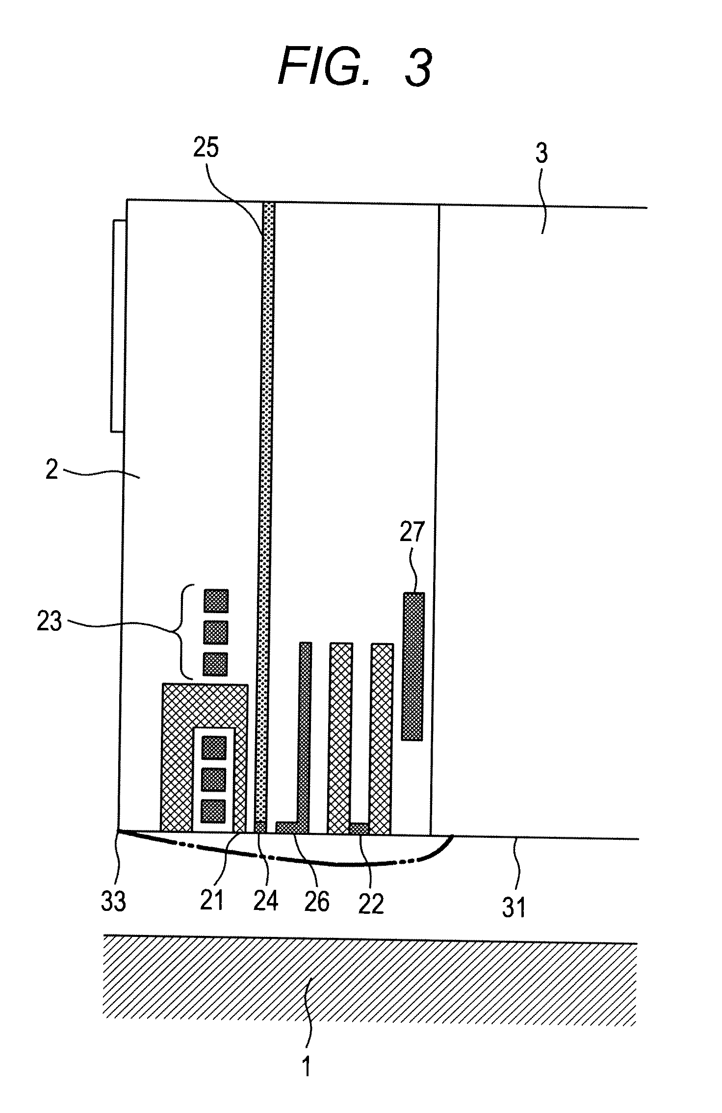
[0040]Next, a first embodiment of the thermally assisted magnetic recording head according to the present invention will be described with reference to FIGS. 3 and 4.

[0041]FIG. 3 is a cross-sectional view of the thermally assisted magnetic recording head 2, taken along a section including a line connecting the middle point of the leading edge 32 and the middle point of the trailing edge 33 in the slider shown in FIG. 2.

[0042]FIG. 4 is a view of the thermally assisted magnetic recording head 2 viewed from the side of the air bearing surface 31.

[0043]The thermally assisted magnetic recording head 2 includes a main magnetic pole 21, a read element 22, a coil 23 for generating magnetic field from the main magnetic pole 21, a near-field transducer 24, a waveguide 25 for guiding a laser beam to the near-field transducer 24, a temperature sensor 26, and a thermal flying-height control (TFC) coil 27.

[0044]The near-field transducer 24 is formed in the vicinity of the main mag...

Example

Second Embodiment

[0054]A second embodiment uses a piezoelectric element as the actuator 54 for controlling the amount of protrusion of the magnetic head 2.

[0055]The second embodiment of the thermally assisted magnetic recording head according to the present invention will be described with reference to FIGS. 6 and 7.

[0056]FIG. 6 is a cross-sectional view of the thermally assisted magnetic recording head 2, taken along a section including a line connecting the middle point of the leading edge 32 and the middle point of the trailing edge 33 in the slider shown in FIG. 2.

[0057]FIG. 7 is a view of the thermally assisted magnetic recording head 2 viewed from the side of the air bearing surface 31.

[0058]The thermally assisted magnetic recording head 2 includes the main magnetic pole 21, the read element 22, the coil 23 for generating a magnetic field from the main magnetic pole 21, the near-field transducer 24, the waveguide 25 for guiding a laser beam to the near-field transducer 24, the...


PUM


Abstract

There is provided a thermally assisted magnetic recording device capable of preventing collision between a thermally assisted magnetic recording head and a disk due to thermal deformation of a near-field transducer. The thermally assisted magnetic recording device includes a temperature sensor for measuring the temperature in the vicinity of the near-field transducer, a table that stores the relationship between temperature and deformation in the vicinity of the near-field transducer, and a control unit. The control unit calculates the deformation in the vicinity of the near-field transducer, from the temperature measured by the temperature sensor and the relationship between temperature and deformation stored in the table. Then, the control unit drives the flying height control actuator according to the calculated deformation to control the distance between the thermally assisted magnetic recording and the disk in order to avoid contact between them.

Description

CLAIM OF PRIORITY[0001]The present application claims priority from Japanese patent application JP2010-129950 filed on Jun. 7, 2010, the content of which is hereby incorporated by reference into this application.BACKGROUND OF THE INVENTION[0002]1. Field of the Invention[0003]The present invention relates to a thermally assisted magnetic recording device. More particularly, the present invention relates to a thermally assisted magnetic recording device provided with a means for preventing a thermally assisted magnetic head from colliding with a disk due to thermal deformation of a near-field transducer (NFT), and for keeping the distance constant between the thermally assisted magnetic recording head and the disk.[0004]2. Description of the Related Art[0005]One technique for significantly increasing the recording density of a magnetic disk is called thermally assisted magnetic recording. Thermally assisted magnetic recording is designed to record data onto a disk by applying heat ove...

Claims


Application Information

Patent Timeline
IPC IPC(8): G11B11/00
CPCG11B5/3106G11B5/3136G11B5/607G11B2005/0021G11B5/6088G11B5/40
Inventor NANIWA, IRIZOMATSUMOTO, TAKUYAKATO, YUKIO
Owner HITACHI LTD
Why Eureka
Try Eureka