Fibrous structural article and manufacturing method thereof

Inactive Publication Date: 2011-12-08
TOYOTA BOSHOKU KK
View PDF5 Cites 4 Cited by
  • Summary
  • Abstract
  • Description
  • Claims
  • Application Information

AI Technical Summary

Benefits of technology

[0011]In the production method of a fibrous structural article of the present invention, since respective fibers are blown and supplied into a forming mold in a hollow box shape from a fiber supplying port, and then at least part of one of the fibers are melted, a fibrous structural article can be readily manufactured in a simple operation using a simple apparatus, which is easier to handle and has a predetermined shape of which is sufficiently kept.
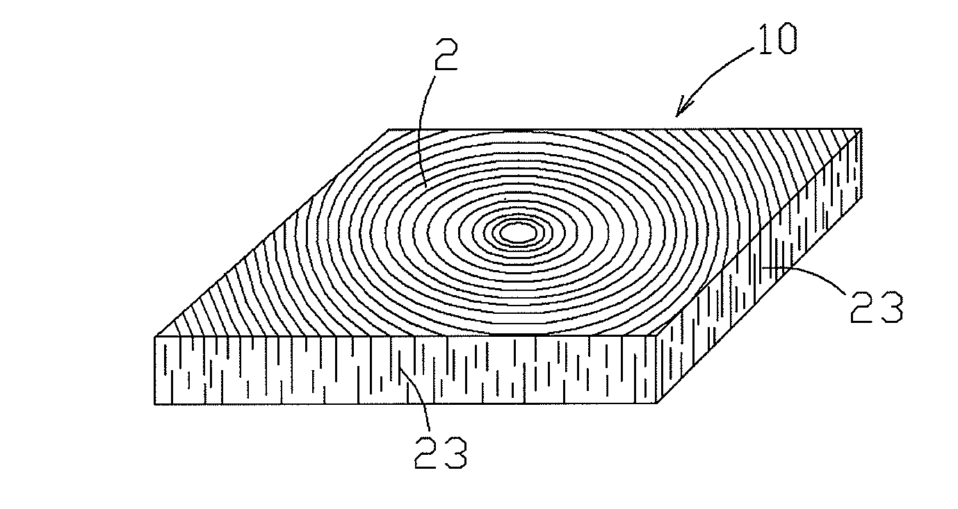
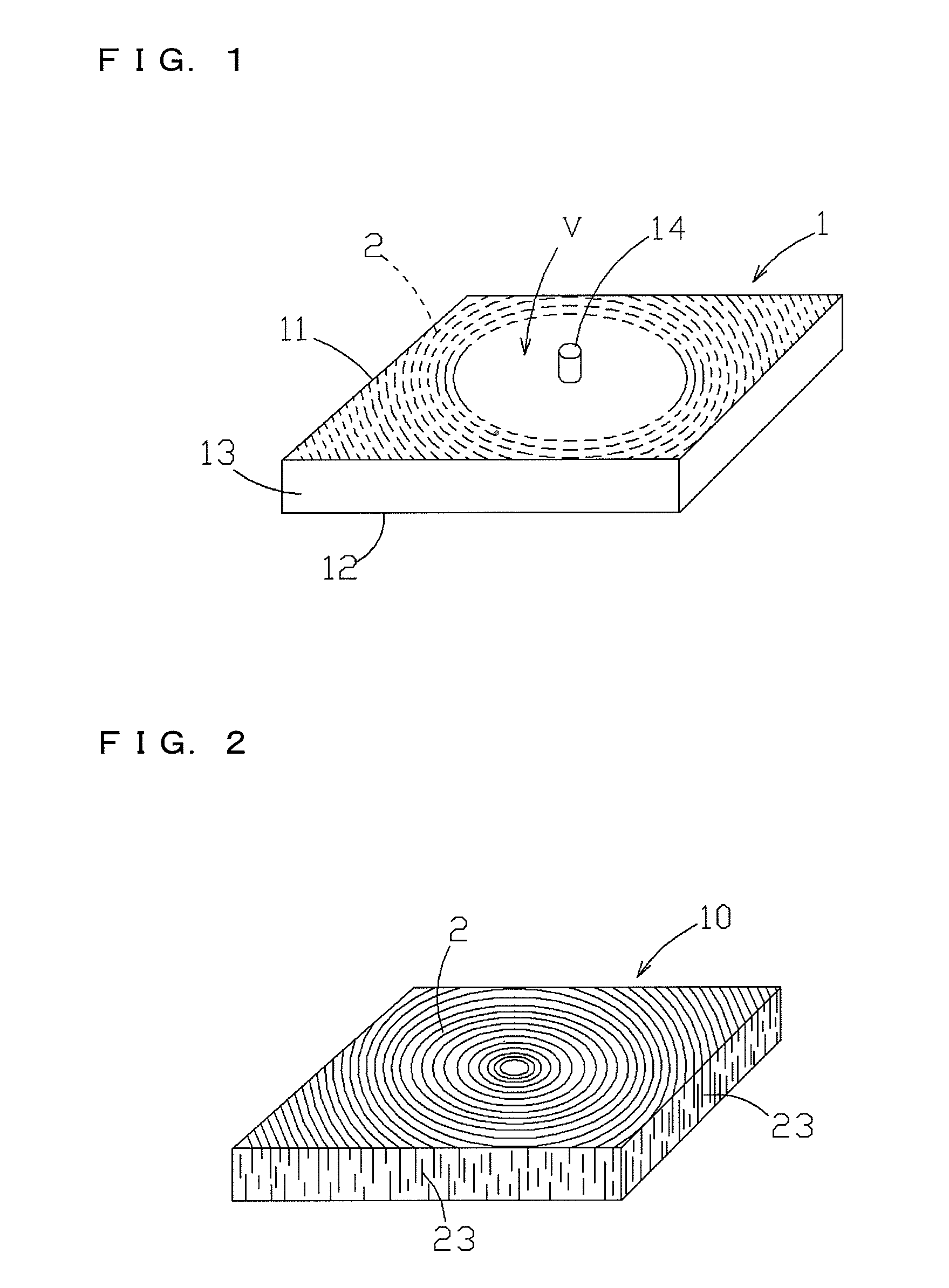
[0012]In the case where at least one of the first short fibers and the second short fibers are arranged in an annual ring centering on a virtual axis, since the stacked first and second short fibers which are supplied about the fiber supplying port are arranged in an annual ring con

Problems solved by technology

This causes such a problem that the accordion web is easily stretched in an inter-layer direction thereof upon application of a pulling force in this direction (see FIG. 16), and the web is occasionally broken at a location between layers (see FIG. 17), so that the web is difficult to handle.
Further, th

Method used


Image

  • Fibrous structural article and manufacturing method thereof
  • Fibrous structural article and manufacturing method thereof
  • Fibrous structural article and manufacturing method thereof

Examples


example 1

[0065]Used were: 40% by weight of polyethylene terephthalate fibers having an average fineness of 3.3 dtex and an average fiber length of 10 mm (trade name “SD150” manufactured by Takayasu Co., Ltd.) as the first short fiber; 40% by weight of thermally fusion-bondable sheath-core type fibers having an average fineness of 2.2 dtex and an average fiber length of 10 mm (trade name “T9611” manufactured by Toray Industries Inc.) as the second short fibers, respectively, each comprising a material at a core portion made of a polyethylene terephthalate having a melting point of 260° C., and a material at a sheath portion made of a copolymerized polyester having a melting point of 110° C.; and 20% by weight of a granular polyurethane foam having a density of 0.015 to 0.030 g / cm3 and a maximum dimension of 15 mm, that was a crushed matter obtained by crushing a massive soft polyurethane foam.

[0066]The first and second short fibers and the granular polyurethane foams were dry blended, and the...

example 2

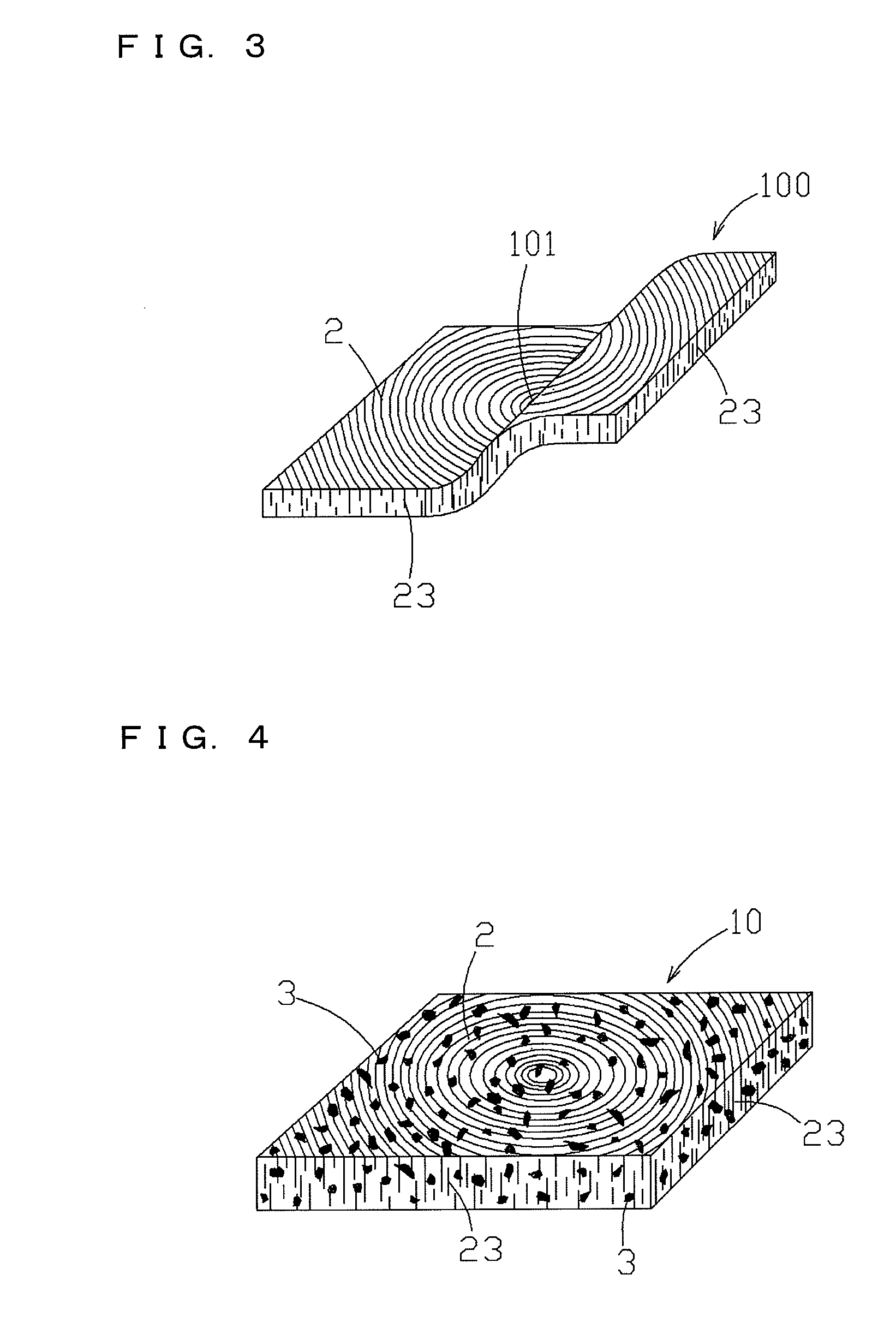
[0068]20% by weight of first short fibers, 20% by weight of second short fibers, and 60% by weight of granular polyurethane foams were dry blended to obtain a mixture, which was fed by air and supplied at a constant rate of 50 g / sec into a forming mold having a mold face following shapes of portions 10a to be pre-molded, thereby forming a pre-molded body 10 having four pre-molded portions 10a as shown in FIG. 13. Thereafter, the pre-molded body 10 having the formed four pre-molded portions 10a was subjected to heating in the same manner as that in Example 1 to manufacture a fibrous molded article 100b for fibrous structural article having the four molded fiber-made portions 100a as shown in FIG. 14. (It is noted that broken lines in an annual ring configuration are omitted in FIG. 14, so as to avoid complication.)

[0069]As described above, particularly when each fibrous structural article is to have a more complicated final shape, it is also possible to manufacture the fibrous molded...


PUM

PropertyMeasurementUnit
Shapeaaaaaaaaaa

Abstract

The present fibrous structural article is a material in a plate-like shape and having multiple fibers adhered to one another, and fibers are oriented from one surface side toward the other surface side of the fibrous structural article, and the fibers are arranged in an annual ring centering on a virtual axis. The present production method of a fibrous structural article comprises a fiber supplying process for blowing and supplying first short fibers and second short fibers, into a forming mold in a hollow box shape and having a first bottom wall, sidewalls and second bottom wall, from a fiber supplying port formed through the first bottom wall, and a melting process for melting at least part of the second short fibers.

Description

INCORPORATION BY REFERENCE[0001]The present application claims priority under 35 U.S.C. §119 of Japanese Patent Application No. 2010-131513, filed on Jun. 8, 2010, the disclosure of which is expressly incorporated by reference herein in its entirety.BACKGROUND OF THE INVENTION[0002]1. Field of the Invention[0003]The present invention relates to a fibrous structural article and a production method thereof. More specifically, the present invention relates to a fibrous structural article that includes depositedly stacked fibers which are oriented from one surface side toward the other surface side of the fibrous structural article and are arranged in an annual ring centering on a virtual axis, such that the fibrous structural article is rarely stretched and broken even upon application of a pulling force thereto in its radial direction to thereby facilitate its handling, and such that a fiber aggregate comprising the depositedly stacked fibers has not been subjected to a compressive fo...

Claims


Application Information

Patent Timeline
IPC IPC(8): B32B5/02B29C67/00B32B3/00B60R13/02D04H1/558D04H1/74
CPCD04H1/541Y10T428/24355D04H1/74D04H1/736D04H1/5412D04H1/5414Y10T428/249921
Inventor UENO, NOBUKAZUBEPPU, YASUHIROTSUBOUCHI, AKIRA
Owner TOYOTA BOSHOKU KK
Why Eureka
Try Eureka