Power storage device

Active Publication Date: 2011-12-08
SEMICON ENERGY LAB CO LTD
View PDF3 Cites 18 Cited by
  • Summary
  • Abstract
  • Description
  • Claims
  • Application Information

AI Technical Summary

Benefits of technology

[0046]According to one embodiment of the disclosed invention, a power storage device h

Problems solved by technology

However, even when a positive electrode active material which includes a phosphate compound having an oli

Method used


Image

  • Power storage device
  • Power storage device
  • Power storage device

Examples


embodiment 1

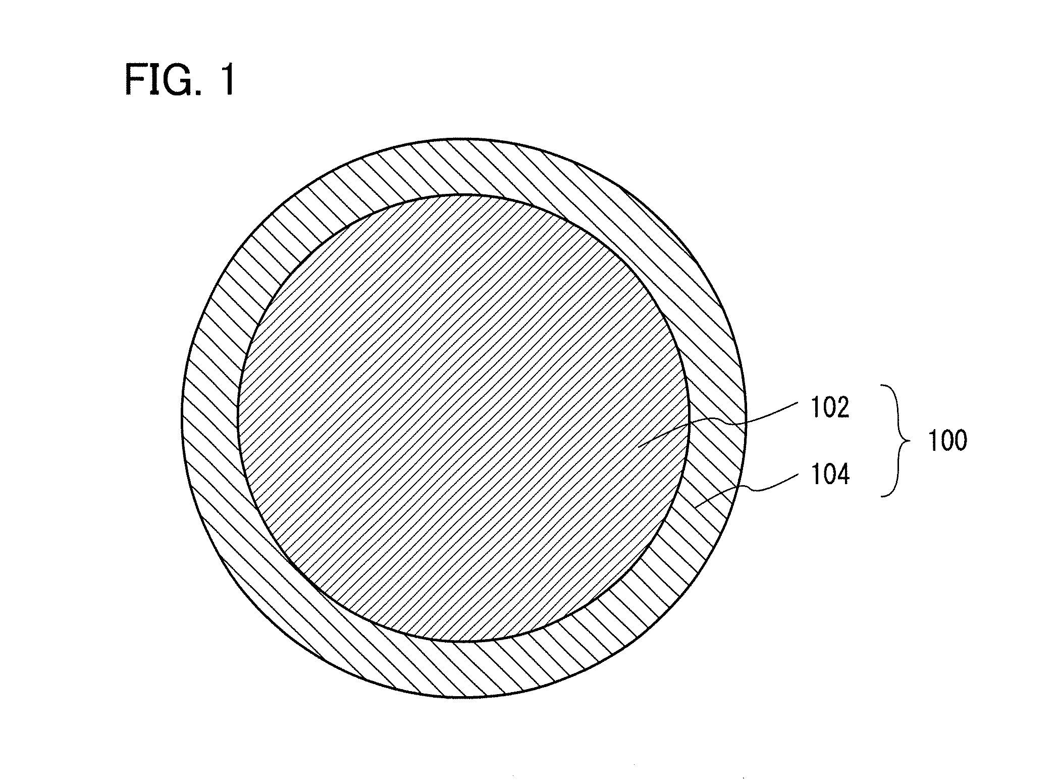
[0064]In this embodiment, a structure of a positive electrode active material in particle form which is one embodiment of the present invention will be described with reference to FIG. 1.

[0065]FIG. 1 is a schematic cross-sectional view of a positive electrode active material in particle form which is one embodiment of the present invention.

[0066]As illustrated in FIG. 1, in this embodiment, a positive electrode active material 100 includes a first region which includes a compound containing lithium and one or more of manganese, cobalt, and nickel (hereinafter, this region is referred to as a first region 102); and a second region which covers a surface of the first region 102 and includes a compound containing lithium and iron (hereinafter, this region is referred to as a second region 104).

[0067]The positive electrode active material is in particle form, and a positive electrode active material layer described later may be formed using a plurality of particles of the positive elect...

embodiment 2

[0082]In this embodiment, a positive electrode active material having higher discharge capacity and higher energy density than the positive electrode active material in Embodiment 1 will be described.

[0083]In this embodiment, the case where both the first region 102 and the second region 104 include a positive electrode active material containing a phosphate compound having an olivine structure is described.

[0084]A substance included in the first region 102 has an olivine structure, and includes lithium, a transition metal, and phosphoric acid (PO4). The transition metal of the first region 102 contains one or more of iron, manganese, cobalt, and nickel and one or more of manganese, cobalt, and nickel. The substance included in the first region 102 is expressed by the general formula, Li1-x1Fey1M1-y1PO4 (x1 is greater than or equal to 0 and less than or equal to 1; M is one or more of Mn, Co, and Ni; and y1 is greater than or equal to 0 and less than 1).

[0085]A substance included in...

embodiment 3

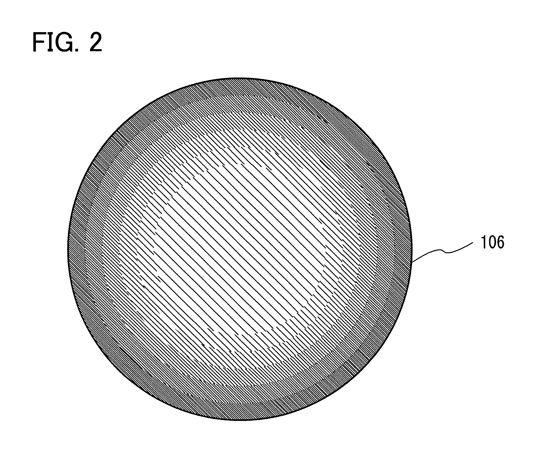
[0090]In this embodiment, a structure of a positive electrode active material which is one embodiment of the present invention will be described with reference to FIG. 2.

[0091]FIG. 2 is a schematic cross-sectional view of a positive electrode active material in particle form which is one embodiment of the present invention.

[0092]As described in FIG. 2, in this embodiment, a positive electrode active material in particle form includes a compound containing lithium (Li), iron (Fe), and a transition metal (one or more of manganese (Mn), cobalt (Co), and nickel (Ni)) and a superficial portion of the positive electrode active material has higher iron concentration than a center portion of the positive electrode active material (hereinafter, this positive electrode active material is referred to as a positive electrode active material 106). Alternatively, a positive electrode active material in particle form includes a compound containing lithium, iron, and a transition metal (one or more...


PUM


Abstract

A power storage device including a positive electrode in which a positive electrode active material is formed over a positive electrode current collector and a negative electrode which faces the positive electrode with an electrolyte interposed therebetween is provided. The positive electrode active material includes a first region which includes a compound containing lithium and one or more of manganese, cobalt, and nickel; and a second region which covers the first region and includes a compound containing lithium and iron. Since a superficial portion of the positive electrode active material includes the second region containing iron, an energy barrier when lithium is inserted into and extracted from the surface of the positive electrode active material can be decreased.

Description

TECHNICAL FIELD[0001]One embodiment of the disclosed invention relates to a power storage device.BACKGROUND ART[0002]The field of portable electronic devices such as personal computers and cellular phones has progressed significantly. The portable electronic device needs a chargeable power storage device having high energy density, which is small, lightweight, and reliable. As such a power storage device, for example, a lithium-ion secondary battery is known. In addition, development of electrically propelled vehicles on which secondary batteries are mounted has also been progressing rapidly from a rise of growing awareness to environmental problems and energy problems.[0003]In a lithium-ion secondary battery, as a positive electrode active material, a phosphate compound having an olivine structure and containing lithium (Li) and iron (Fe), manganese (Mn), cobalt (Co), or nickel (Ni), such as lithium iron phosphate (LiFePO4), lithium manganese phosphate (LiMnPO4), lithium cobalt pho...

Claims


Application Information

Patent Timeline
IPC IPC(8): H01M4/64H01M4/58
CPCH01M4/136Y02E60/122H01M4/366H01M4/5825H01M2004/028H01M10/052H01M4/0404H01M10/0525H01M10/058Y02E60/10Y02P70/50H01M2220/30
Inventor KAWAKAMI, TAKAHIRO
Owner SEMICON ENERGY LAB CO LTD
Why Eureka
Try Eureka