Measurement of auditory evoked responses

a technology of auditory evoked responses and measurement methods, applied in the field of electroencephalogram signal measurement, can solve the problems of limited sensitivity in detecting children with a possible hearing loss, low sensitivity of the detection method, and inability to test the integrity of the neural pathway after the cochlea leading to the auditory cortex, etc., and achieve the effect of better conta

Inactive Publication Date: 2011-12-08
CORDIAL MEDICAL EURO
View PDF5 Cites 21 Cited by
  • Summary
  • Abstract
  • Description
  • Claims
  • Application Information

AI Technical Summary

Benefits of technology

[0025]Another advantageous effect of the invention is that the electrodes can be monitored continuously by visual inspection during the whole recording session when the subject or patient is lying on his or her back.
[0026]It must be noted that the invention is intended for, but not necessarily restricted to, healthy persons having two ears and two eyes without substantive anatomic deviations.
[0027]In an embodiment of the method in accordance with the invention at least one of the first region and the second region is further defined as a fictitious strip having a midline, the midline extending from an external auditory meatus (also being referred to as outer ear canal, auditory duct, and auditory canal) of the respective ear in a direction towards a nose. Throughout the description the word “strip” must be interpreted as an elongate shape, but not necessarily having a 100% rectangular shape. Here it must be noted that the strip is defined with respect to a projection of the head on a flat surface. The height of the ear does not necessarily need to be equal to the vertical height of the nose. This embodiment further restricts the size of the regions to a strip-shaped region having a height, which is substantially constant over its length (it must be kept in mind that the face of a patient is not flat, but follows a 3-dimensional contour, differing from subject to subject). The strip is defined as a part of this surface. The midline which runs from the external auditory meatus (in projection on the flat surface) to the nose may extend in a substantial horizontal direction, but this is not necessary and also depends on the anatomy of the subject or patient. In any case this embodiment defines a region on the head where the placement of the electrodes is easier and provides a better contact, in particular because the surface is relatively flat within the strip.
[0028]In an embodiment of the method in accordance with the invention the strip has a width of 6 centimeters, and preferably 4 centimeters, and even more preferably 2 centimeters. Placement of the electrodes is easier and more effective within the region in accordance with this embodiment.
[0029]In an embodiment of the method in accordance with the invention a heart-heart distance between each respective one of the first and second electrodes and the respective external auditory meatus lies in the range between 1 and 2 centimeters. Experiments have shown that this region is the best for placement of the electrodes.
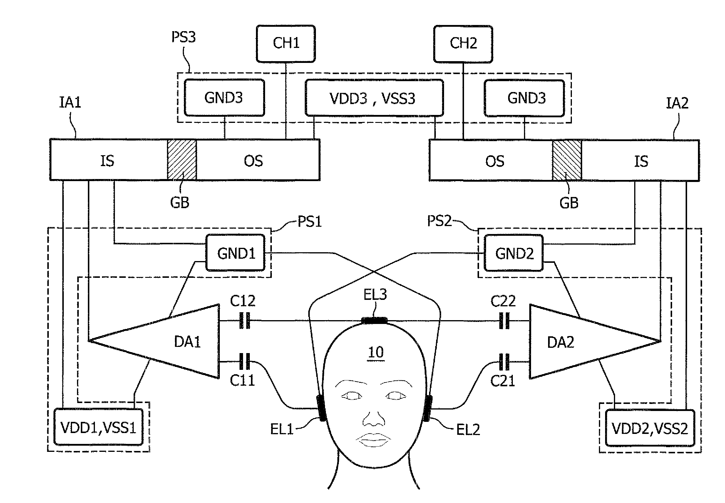
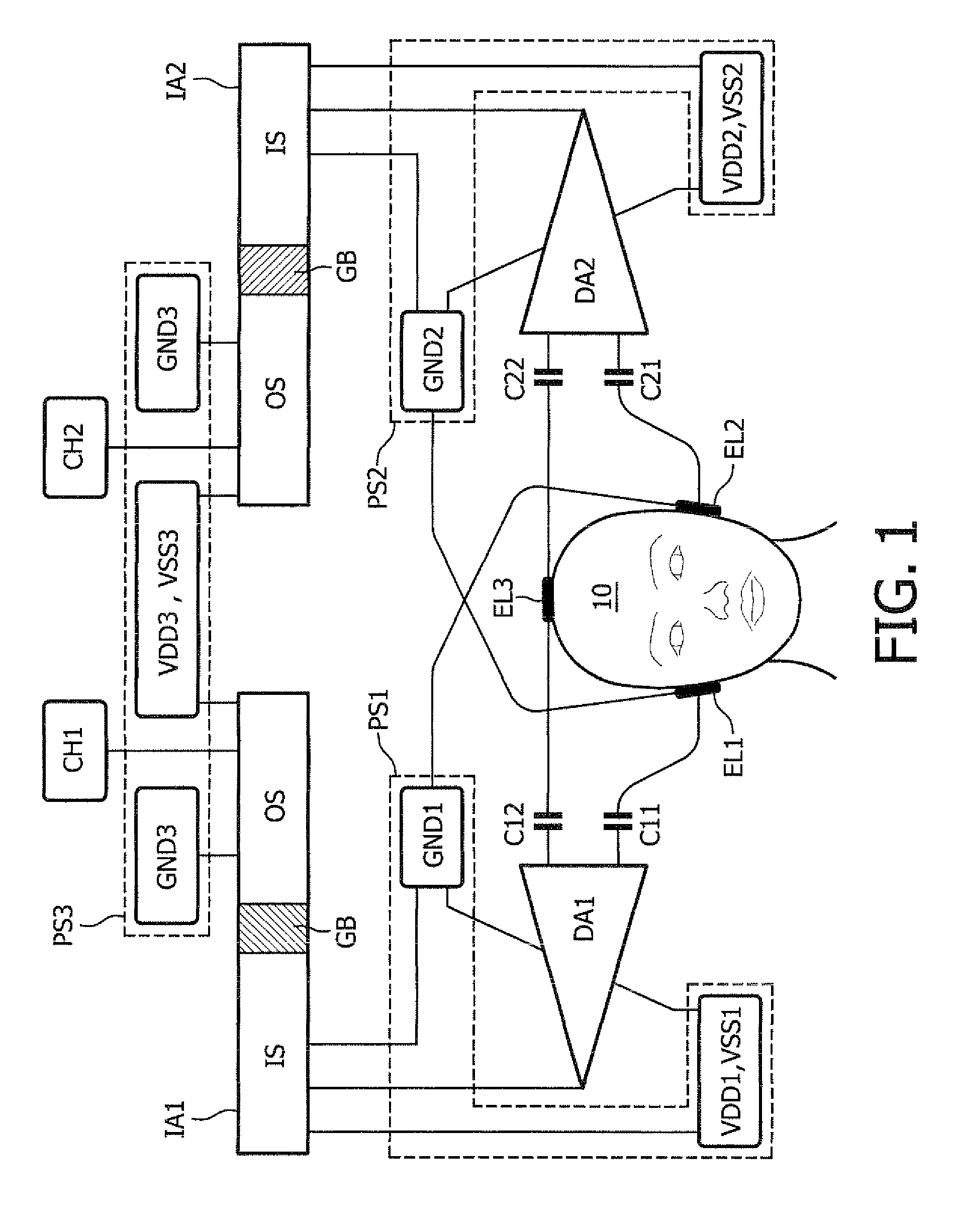
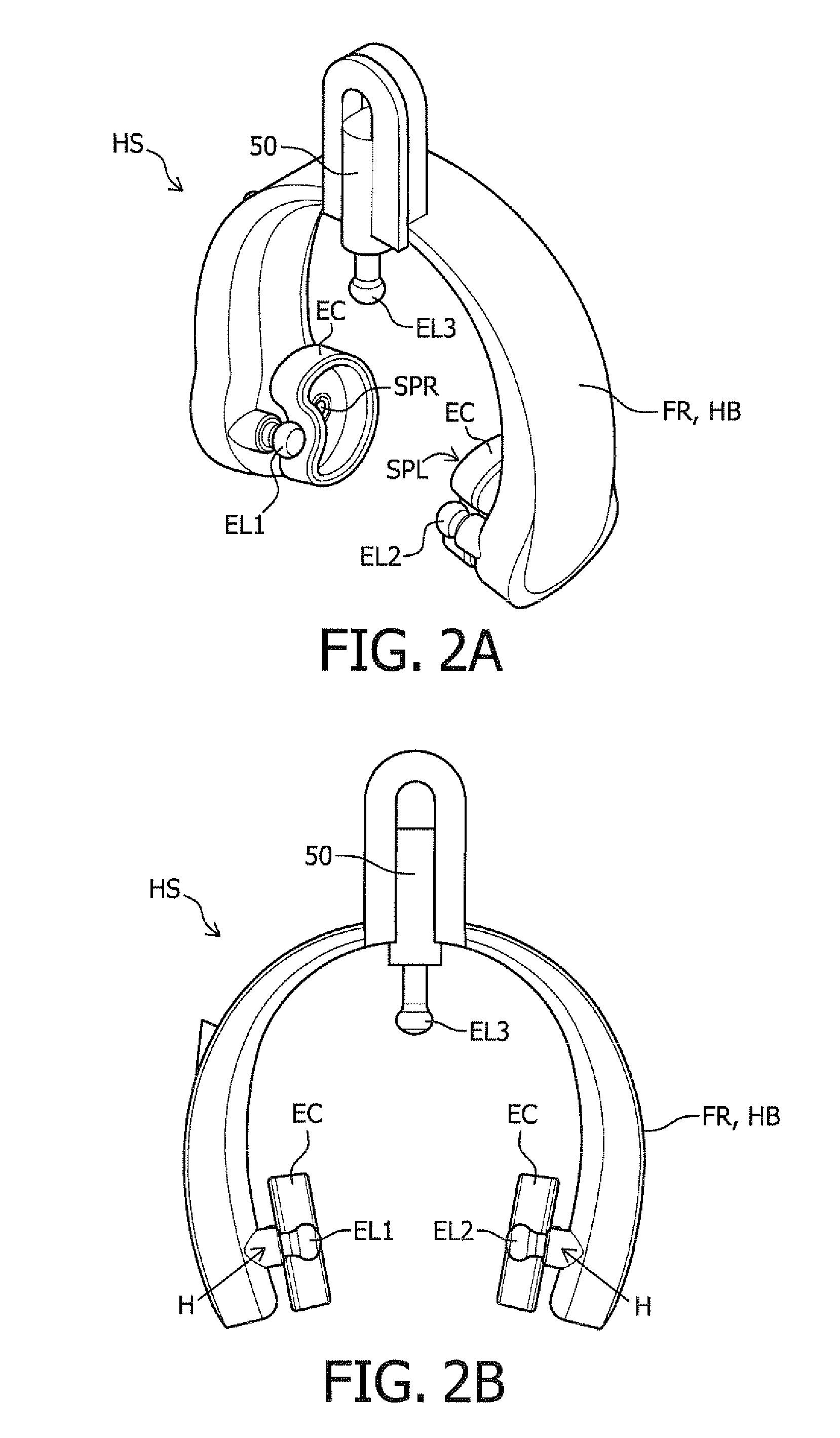
[0030]In an embodiment of the method in accordance with the invention the third electrode is positioned on the midline of the head of the subject or patient. Placing the third electrode on the midline of the head has the advantage that the integration with the first and the second electrode in a frame or head-set (that can be put on the head to fix locations of the electrodes) becomes easier. The midline follows the contour of the head and extends from the forehead to the neck of the subject or patient.

Problems solved by technology

This technique is cheap, but has a limited sensitivity in detecting children with a possible hearing loss: A pass means that the cochlea is OK, but the integrity of the neural pathway after the cochlea leading to the auditory cortex is not tested.
This is a big disadvantage of the OAE.
Hence, the post-acquisition processing of the EEG signals is limited to that number of EEG sweeps.
However, it has been found by the inventors of the present system, that these configurations surprisingly reduce common mode rejection and thereby, increases noise and artifacts.
Furthermore an increased number of electrodes increases the risk of bad electrode contact to the skin of the subject during hearing screening which increases testing time.
However, as such, the apparatus is complex to use.

Method used


Image

  • Measurement of auditory evoked responses
  • Measurement of auditory evoked responses
  • Measurement of auditory evoked responses

Examples


first embodiment

[0133]FIG. 4a schematically illustrates a location of the first and second electrodes in accordance with the invention. In this figure the first region R1 and second region R2 for the first electrode are strip-shaped and substantially between the respective ear and the respective eye. The strip has a (virtual) midline ML which extends from an external auditory meatus of the respective ear to the nose (as illustrated in the figure). The strip has a width of about 6 centimeters.

second embodiment

[0134]FIG. 4b schematically illustrates a location of the first and second electrodes in accordance with the invention. This figure illustrates the first (further restricted with respect to FIG. 4a) region R1 and the second (further restricted with respect to FIG. 4a) region R2, wherein the strip has a width of about 4 centimeters. In a further embodiment the strip has a width of about 2 centimeters. Positioning the respective electrodes within this region further facilitates easy integration in the headset, but at the same time enables a better contact between the electrodes and the skin and also better visual inspection during the measurements. The restricted regions as illustrated in FIG. 4b generally more coincide with the cheek bone and are very suitable for placing electrodes.

third embodiment

[0135]FIG. 4c schematically illustrates a location of the first and second electrodes in accordance with the invention. This figure illustrates the first (further restricted with respect to FIG. 4b) region R1 and the second (further restricted with respect to FIG. 4b) region R2, wherein the strip has a width of about 2 centimeters. The first (even further restricted) region R1″ and the second (even further restricted) region R2″ substantially coincide with a location of the joint between the skull and the jaw. Experiments have shown that this region is particularly advantageous for positioning an electrode, while obtaining a very good contact (and thereby a very good signal-to-noise ratio).

[0136]FIG. 5 shows a shielded electrode in accordance with yet another embodiment of the invention. The shielded electrode comprises an electrode EL having a sensing area SAE which is connected to a signal wire WR (which is on its turn coupled to an amplifier). An electrically conductive shield (e...


PUM


Abstract

The invention relates to a method of measuring an electroencephalogram signal in response to an auditory stimulus applied to a subject or patient (99), wherein the method uses at the most a first electrode (EL1), a second electrode (EL2), a third electrode (EL3). The method comprises: i) positioning the first electrode (EL1) on the head (10) of the patient or subject (99) in a first region (R1) extending substantially between a right ear and a right eye; ii) positioning the second electrode (EL2) on the head (10) of the subject or patient (99) in a second region (R2) extending substantially between a left ear and a left eye; iii) positioning the third electrode (EL3) on the head (10) of the subject or patient (99) in a third region (Cz), the third region (Cz) being different from the first region (R1) and the second region (R2); iv) applying the auditory stimulus to at least one ear of the subject or patient (99); v) measuring a first potential difference between the first electrode (EL1) and the third electrode (EL3) in response to the auditory stimulus to obtain a first electroencephalographic signal, and measuring a second potential difference between the second electrode (EL2) and the third electrode (EL3) in response to the auditory stimulus to obtain a second electroencephalographic The invention further relates to a method of hearing screening a subject or patient, comprising such method. The invention also relates to a measurement system (such as a hearing screener) for carrying out such method and to an apparatus (head-set) for use in such system. The invention provides for an improved method of measuring an electroencephalogram signal in response to an auditory stimulus applied to a subject or patient, in particular where two channels are measured using only three electrodes.

Description

FIELD OF THE INVENTION[0001]The invention relates to a method of measuring an electroencephalogram signal in response to an auditory stimulus applied to a subject or patient, wherein the method uses at the most a first electrode, a second electrode, a third electrode. The invention also relates to a hearing screen method comprising such method. The invention further relates to a measurement system for carrying out such method, and to a hearing screener comprising such measurement system. The invention also relates to an apparatus for use in such measurement system or hearing screener.BACKGROUND OF THE INVENTION[0002]Methods of measuring auditory evoked responses on the head of a patient are known, for instance from the technical field of hearing screening. Hearing is an essential feature to enable communication and to enjoy music. The ability to hear is also essential to develop language and to understand speech. Although it is not until the age of four years that a child is able to...

Claims


Application Information

Patent Timeline
Patent Type & Authority Applications(United States)
IPC IPC(8): A61B5/0484
CPCA61B5/6814A61B2562/182A61B5/121A61B5/04845A61B5/04004A61B5/30A61B5/38A61B5/31
Inventor VAN HEK, DIRKVAN DER REIJDEN, CHRISTOPH
Owner CORDIAL MEDICAL EURO
Why Eureka
Try Eureka