Electric drive vehicle, system and method

a technology of electric drive and electric motor, applied in hybrid vehicles, process and machine control, instruments, etc., can solve the problems of limiting the number of vehicles that may be operated, the limited number of engines that may be operated at a given moment, etc., and achieves the reduction of the need to operate a combustion engine, reducing the need for operating the engine of the vehicle, and increasing the amount of energy.

Active Publication Date: 2011-12-08
GE GLOBAL SOURCING LLC
View PDF5 Cites 37 Cited by
  • Summary
  • Abstract
  • Description
  • Claims
  • Application Information

AI Technical Summary

Benefits of technology

[0004]Methods and systems are provided for operating an electric drive for a vehicle, such as a mining apparatus. In one embodiment, the electric drive comprises a motor capable of propelling the vehicle, and an energy storage device coupled to the motor. The energy storage device may be selectively couplable to a catenary line, wherein the catenary line is capable of supplying electrical power to the vehicle and to the energy storage device. The electric drive system of the vehicle may then be controlled based on the operating mode of the vehicle. In one embodiment, the vehicle includes a mining device that is operable to be powered by energy from one or more of the catenary line and the energy storage device. In this configuration, during some modes, the motor may be powered by the energy storage device thereby propelling the vehicle, while during other modes, the external power source may power the motor while also recharging the energy storage device. Further still, in some embodiments, power from the energy storage device and the external power source may be combined. In this way, by providing power to the electric drive from an board energy storage device, the need to operate a combustion engine is reduced.
[0005]In one example, the vehicle is a mining vehicle including a mining ore cart. The mining vehicle is operated in a mining environment, such as a mining shaft, wherein emissions and ventilations are stringently regulated. The mining vehicle is configured with a hybrid electric drive including an engine, a traction motor for propelling the wheels of the vehicle, a hermetically sealed energy storage device including one or more battery modules, and a moto

Problems solved by technology

In such environments, the use of internal combustion engines may be prohibited, and/or the number of engines that may be operated at a

Method used


Image

  • Electric drive vehicle, system and method
  • Electric drive vehicle, system and method
  • Electric drive vehicle, system and method

Examples


first embodiment

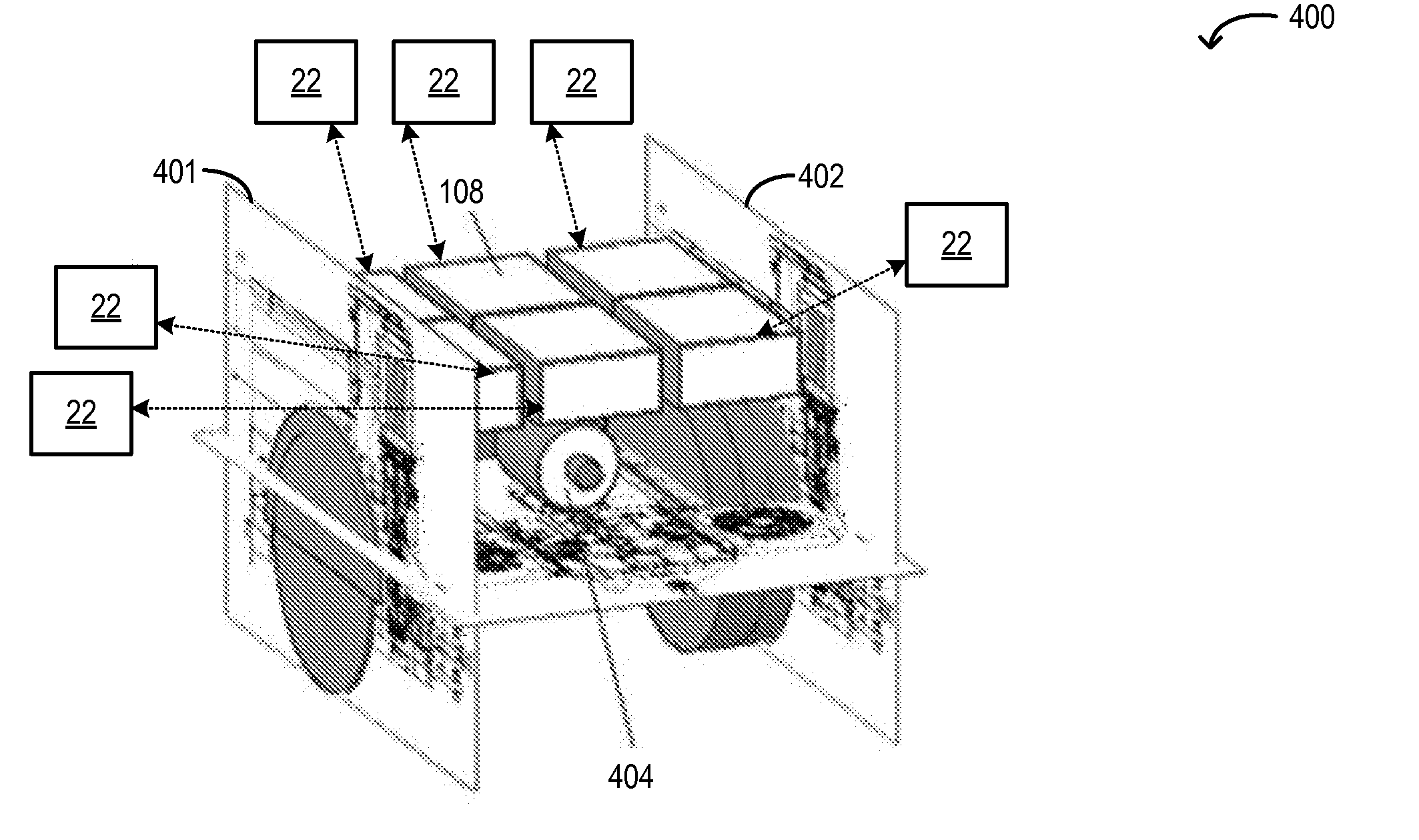
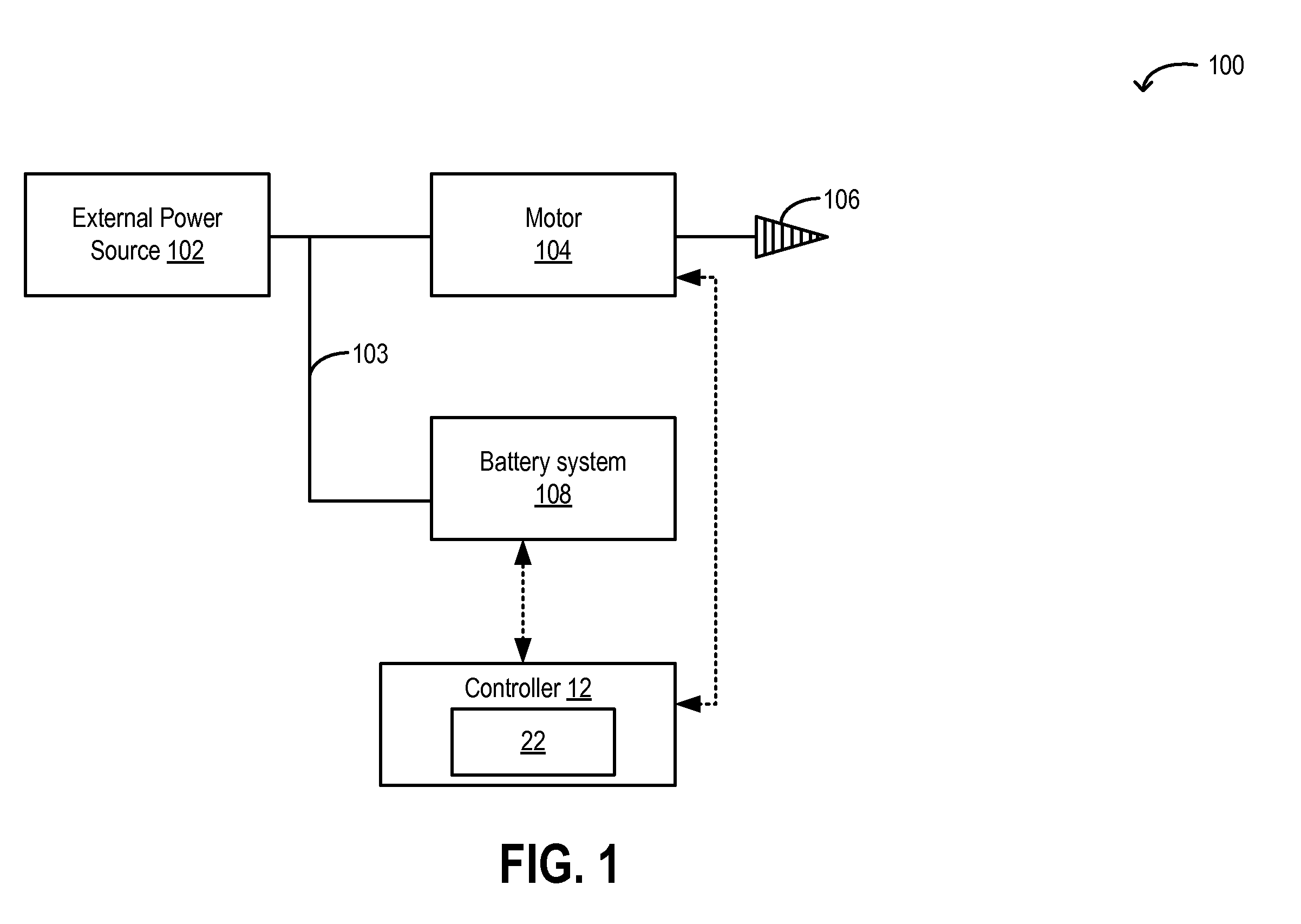
[0016]FIG. 1 shows an electric drive system 100 for a vehicle. As a non-limiting example, the vehicle is shown as a mining vehicle including a drill configured for electric propulsion. The electric drive system 100 includes one or more electric motors 104. The motors 104 include a fraction motor capable of propelling the vehicle as well as a motor (e.g., drill motor) for operating a mining device associated with the mining vehicle, herein drill 106. In the depicted example, the mining device is used to drill into the face of a mine wall. The electric drive system 100 further includes an energy storage device 108, herein depicted as a battery system, coupled to electric motor 104. As elaborated with reference to FIGS. 2-3, the mining vehicle may be a hybrid electric system wherein electric drive system 100 is a hybrid electric drive system coupled to an internal combustion engine of the vehicle. In alternate embodiments, where electric drive system is not coupled to a vehicle engine,...

embodiment 200

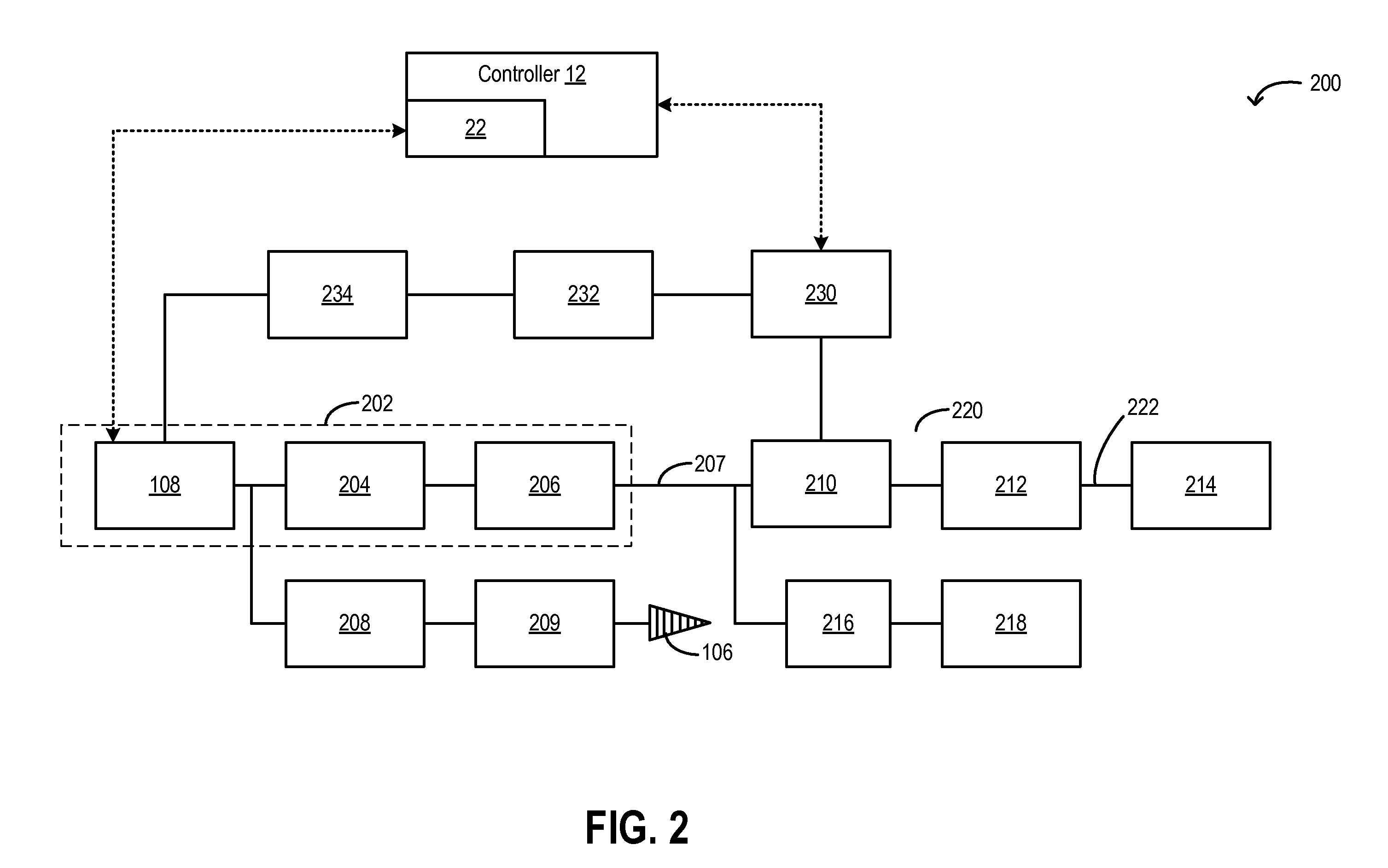
[0026]Turning now to FIG. 2, embodiment 200 shows energy storage device 108 coupled to a traction motor 206 via a first inverter 204 and to a drill motor 209 powering mining device (e.g., drill) 106 though a second different inverter 208. As previously elaborated with reference to FIG. 1, one or more energy storage banks of energy storage device 108 may be managed by battery management system 22. As such, the combination of energy storage device 108, traction motor 206, and first inverter 204 may define an electric power pack 202. Traction motor 206 can power wheels 214 either directly through drive train 220, or through transmission 210. In the depicted example, motor shaft 207 of traction motor 206 is coupled to hydrodynamic transmission 210. A suitable traction motor may be an AC motor (as depicted) or a DC motor. In the event that the motor is an AC motor (as depicted herein), use of an inverter paired with the traction motor allows the DC input from the energy storage device to...


PUM


Abstract

An electric drive system is provided for use in a vehicle that is operated in environments with stringent emissions and ventilation regulations. In one embodiment, the electric drive system comprises a motor capable of propelling the vehicle and an energy storage device coupled to the motor, and selectively couplable to a catenary line, wherein the catenary line is capable of supplying electrical power to the vehicle and to the energy storage device. Additionally, the vehicle includes a mining device that is operable to be powered by energy from one or more of the catenary line and the energy storage device.

Description

CROSS-REFERENCE TO RELATED APPLICATIONS[0001]This application claims priority to U.S. Provisional Application 61 / 310,699, filed on Mar. 4, 2010, the entirety of which is hereby incorporated by reference herein for all purposes.FIELD[0002]The subject matter disclosed herein relates to electric drive systems, and methods of operating such an electric drive system.BACKGROUND[0003]Vehicles including internal combustion engines may be operated in environments, such as mining shafts, which have stringent emissions and ventilation regulations. In such environments, the use of internal combustion engines may be prohibited, and / or the number of engines that may be operated at a given moment may be limited. As such, this also limits the number of vehicles that may be operated at a given moment in that environment.BRIEF DESCRIPTION OF THE INVENTION[0004]Methods and systems are provided for operating an electric drive for a vehicle, such as a mining apparatus. In one embodiment, the electric dr...

Claims


Application Information

Patent Timeline
IPC IPC(8): B60L15/00B60L9/00B60M1/12B60L11/18
CPCE21F13/00B60L1/20Y02T10/7005Y02T90/14Y02T90/121B60L11/1801B60L11/1837B60L2200/40Y02T90/128Y02T10/7072B60L50/53B60L53/32E21F17/06Y02T90/12Y02T10/70
Inventor BASTIEN, BERTRAND
Owner GE GLOBAL SOURCING LLC
Why Eureka
Try Eureka